Clusters
Overview
Infrastructure > Clusters is for creating and managing Kubernetes Clusters, HPE Morpheus Enterprise manager Docker Clusters, KVM Clusters, or Cloud specific Kubernetes services such as EKS, AKS and GKE.
Cluster Types
Name |
Description |
Provider Type |
Kubernetes Cluster |
Provisions by default a Kubernetes cluster consisting of 1 Kubernetes Master and 3 Kubernetes Worker nodes. Additional system layouts available including Master clusters. Custom layouts can be created. |
Kubernetes |
Docker Cluster |
Provisions by default a Morpheus controlled Docker Cluster with 1 host. Additional hosts can be added. Custom layouts can be created. Existing Morpheus Docker Hosts are automatically converted to Clusters upon 4.0.0 upgrade. |
Docker |
EKS Cluster |
Amazon EKS (Elastic Kubernetes Service) Clusters |
Kubernetes |
AKS Cluster |
Azure AKS (Azure Kubernets Service) Clusters |
Kubernetes |
Ext Kubernetes |
Brings an existing (brownfield) Kubernetes cluster into HPE Morpheus Enterprise |
Kubernetes |
GKE Cluster |
Google Cloud GKE (Google Kubernetes Engine) Clusters |
Kubernetes |
HVM Cluster |
A KVM-based virtualization solution. See the detailed section below on HVM Clusters for complete use documentation. |
KVM |
Note
Refer to clusterLayouts for supported Clouds per Cluster Type.
Requirements
Morpheus Role permission
Infrastructure: Clusters > Fullrequired for Viewing, Creating, Editing and Deleting Clusters.Morpheus Role permission
Infrastructure: Clusters > Readrequired for Viewing Cluster list and detail pages.
Cluster Permissions
- Cluster Permissions
Each Cluster has Group, Tenant and Service Plan access permissions settings (“MORE” > Permissions on the Clusters list page).
- Namespace Permissions
Individual Namespaces also have Group, Tenant and Service Plan access permissions settings
HVM Clusters
An HVM cluster is a hypervisor clustering technology utilizing KVM. Beginning with just a few basic Ubuntu boxes, HPE Morpheus Enterprise can create a cluster of hypervisor hosts complete with monitoring, failover, easy migration of workloads across the cluster, and zero-downtime maintenance access to hypervisor host nodes. All of this is backed by HPE Morpheus Enterprise Tenant capabilities, a highly-granular RBAC and policy engine, and Instance Type library with automation workflows.
Features
Host Features
Automated HVM cluster provisioning
CEPH storage configuration for multi-node clusters
CEPH summary, a high-level dashboard of CEPH components and status
DRS, automatic rebalancing of clusters based on resource consumption
Compatibility validation of network and storage devices at time of cluster provisioning
Hypervisor console
Configuration and deployment of OVS networks (VLANs)
Cluster and individual host monitoring
Add hosts to existing clusters
Console support for cluster hosts
Add, edit and remove networks and data stores from clusters
Gracefully take hosts out of service with maintenance mode
Migration of workloads across hosts
Configurable automatic failover of running workloads when a host is lost
Ability to add and provision to fibre channel storage resources or iSCSI storage resources via GFS2 filesystem
Integration with HPE Morpheus Enterprise costing
Governance through HPE Morpheus Enterprise RBAC, Tenancy, and Policies
VM Features
Workload provisioning and monitoring (Linux or Windows workloads)
Console support for running workloads
Affinity placement, pin VMs to hosts
Brownfield discovery of existing VMs
Reconfigure VM sizing
Disk migration across datastores
UEFI support
Migration of VMs across hosts
Configure automatic failover for individual VMs in the event a host is lost
Reconfigure running workloads to resize plan, add/remove disks, and add/remove network interfaces
Backup and restore HVM workloads, with optional synthetic full backups
Clone VMs
Take snapshots and revert to snapshots
HPE Morpheus Enterprise library and automation support
Integration with HPE Morpheus Enterprise costing features
Base Cluster Details
An HVM cluster using the hyperconverged infrastructure (HCI) Layout consists of at least three hosts. Physical hosts are recommended to experience full performance of the HVM cluster solution. In smaller environments, it is possible to create an HVM cluster with three nested virtual machines, a single physical host (non-HCI only), or a single nested virtual machine (non-HCI only) though performance may be reduced. With just one host it won’t be possible to migrate workloads between hosts or take advantage of automatic failover. Currently, a host must be a pre-existing Ubuntu 22.04 box with environment and host system requirements contained in this section. HPE Morpheus Enterprise handles cluster configuration by providing the IP address(es) for your host(s) and a few other details. Details on adding the cluster to HPE Morpheus Enterprise are contained in the next section.
Hardware Requirements
Operating System: Ubuntu 22.04
CPU: One or more 64-bit x86 CPUs, 1.5 GHz minimum with Intel VT or AMD-V enabled
Memory: 4 GB minimum. For non-converged Layouts, configure HVM hosts to use shared external storage, such as an NFS share or iSCSI target. Converged Layouts utilize Ceph for clustered storage and require a 4 GB minimum memory per Ceph disk
Disk Space: For converged storage, a data disk of at least 500 GB is required for testing. More storage will be needed for production clusters. An operating system disk of 15 GB is also required. Clusters utilizing non-converged Layouts can configure external storage (NFS, etc.) while HPE Morpheus Enterprise will configure Ceph for multi-node clusters
Network Connectivity: HVM hosts must be assigned static IP addresses. They also need DNS resolution of the HPE Morpheus Enterprise appliance and Internet access in order to download and install system packages for HVM dependencies, such as KVM, Open vSwitch (OVS), and more
Note
Ubuntu 22.04 uses netplan for networking and it is the responsibility of the customer to establish recommended networking configurations prior to provisioning an HVM cluster. To configure a static IP address, change into the directory holding the config files (cd /etc/netplan) and edit the existing configuration file (/etc/netplan/50-cloud-init.yaml or /etc/netplan/00-installer-config.yaml or /etc/netplan/01-netcfg.yaml). If desired, backup the existing configuration prior to editing it (cp /etc/netplan/<file-name>.yaml /etc/netplan/<file-name>.yaml.bak). For additional information on configuration file formatting, refer to netplan documentation. Once the configuration is updated, validate and apply it (netplan try). The try command will validate the configuration and apply it if it’s valid. If invalid, it will automatically be rolled back.
Note
Clustered storage needs as much network bandwidth as possible. Network interfaces of at least 10 Gbps with jumbo frames enabled are required for clustered storage and for situations when all traffic is running through the management interface (when no compute or storage interface is configured). It’s highly likely that performance will be unacceptable with any lower configurations.
Description |
Source |
Destination |
Port |
Protocol |
|---|---|---|---|---|
HPE Morpheus Enterprise Agent communication with the HPE Morpheus Enterprise appliance |
HVM Host |
HPE Morpheus Enterprise appliance server |
443 |
TCP |
HVM host configuration and management |
HPE Morpheus Enterprise appliance server |
HVM Host |
22 |
TCP |
HVM interhost communication for clustered deployments |
HVM Host |
HVM Host |
22 |
TCP |
HPE Morpheus Enterprise server SSH access for deployed virtual machines |
HPE Morpheus Enterprise appliance server |
HVM-hosted virtual machines |
22 |
TCP |
HPE Morpheus Enterprise server WinRM (HTTP) access for deployed virtual machines |
HPE Morpheus Enterprise appliance server |
HVM-hosted virtual machines |
5985 |
TCP |
HPE Morpheus Enterprise server WinRM (HTTPS) access for deployed virtual machines |
HPE Morpheus Enterprise appliance server |
HVM-hosted virtual machines |
5986 |
TCP |
Ceph Storage |
HVM Host |
HVM Host |
3300 |
TCP |
Ceph Storage |
HVM Host |
HVM Host |
6789 |
TCP |
Ceph MDS/OSD |
HVM Host |
HVM Host |
6800-7300 |
TCP |
Example Cluster Deployment
In this example cluster, each host box consists of:
4 vCPU
16 GB memory
20 GB OS boot disk
250 GB data disk (deployed to
/dev/sdb)3 network interfaces for management, storage, and compute traffic (set to
eth0,eth1, andeth2, respectively, in this example. Your environment may differ.)
Note
250 GB data disks used in this example are simply for demonstration purposes. A typical test cluster should consist of at least 500 GB storage and more will be required for production. Do not raid disks on physical servers. Currently, only one data disk may be used, which is given in the DATA DEVICE configuration during cluster setup. In the very near future, an update will be provided to allow multiple data disks to be used. These will be added to the total Ceph storage in one large volume. Until that update, only one data disk may be given in the configuration.
HVM clusters must also live in HPE Morpheus Enterprise-type Clouds (See Infrastructure > Clouds). A pre-existing HPE Morpheus Enterprise Cloud may be used or a new Cloud could be created to handle HVM management.
Provisioning the Cluster
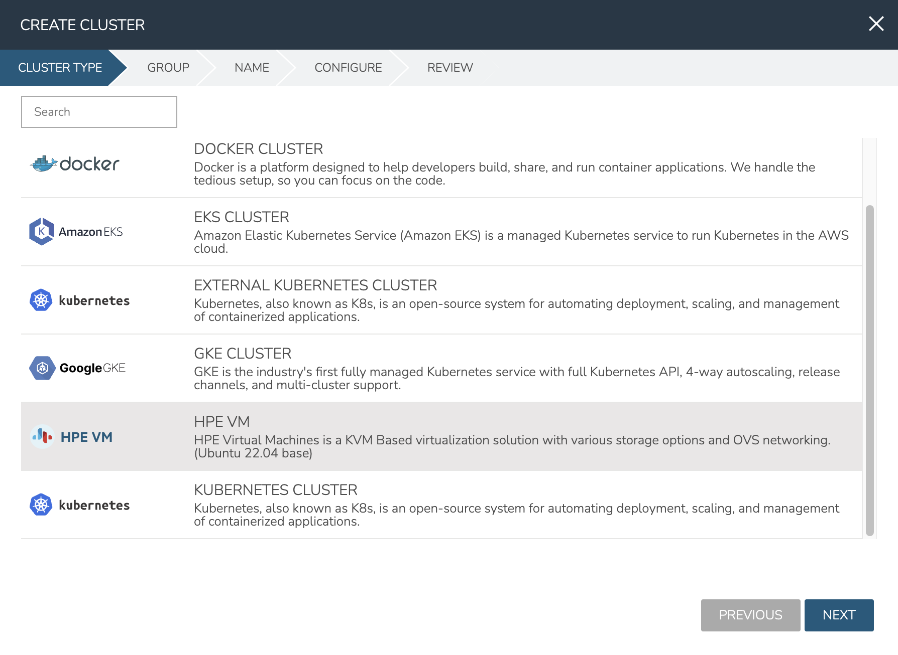
As mentioned in the previous section, this example is starting with three provisioned Ubuntu 22.04 boxes. I also have a HPE Morpheus Enterprise-type Cloud to house the cluster. Begin the cluster creation process from the Clusters list page (Infrastructure > Clusters). Click + ADD CLUSTER and select “HVM”.
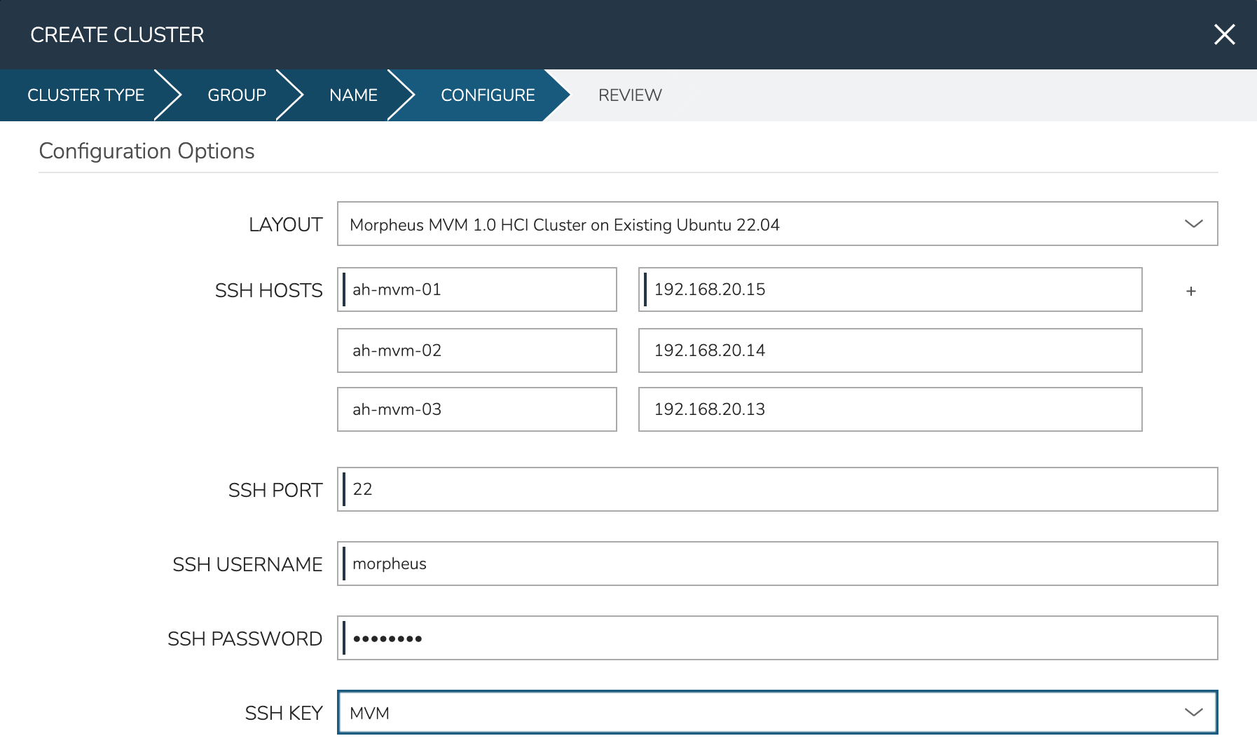
HPE Morpheus Enterprise gives the option to select a hyperconverged infrastructure (HCI) LAYOUT or non-HCI. In this example, the HCI Layout is used (requires a three-node minimum). Next, configure the names and IP addresses for the host boxes (SSH HOST). The SSH HOST name configuration is simply a display name in HPE Morpheus Enterprise, it does not need to be a hostname. By default, configuration space is given for three hosts which is what this example cluster will have. You must at least configure one and it’s possible to add more by clicking the (+) button. The SSH PORT is pre-configured for port 22, change this value if applicable in your environment. Next, set a pre-existing user on the host boxes (SSH USERNAME and SSH PASSWORD) and SSH KEY. Use a regular user with sudo access.
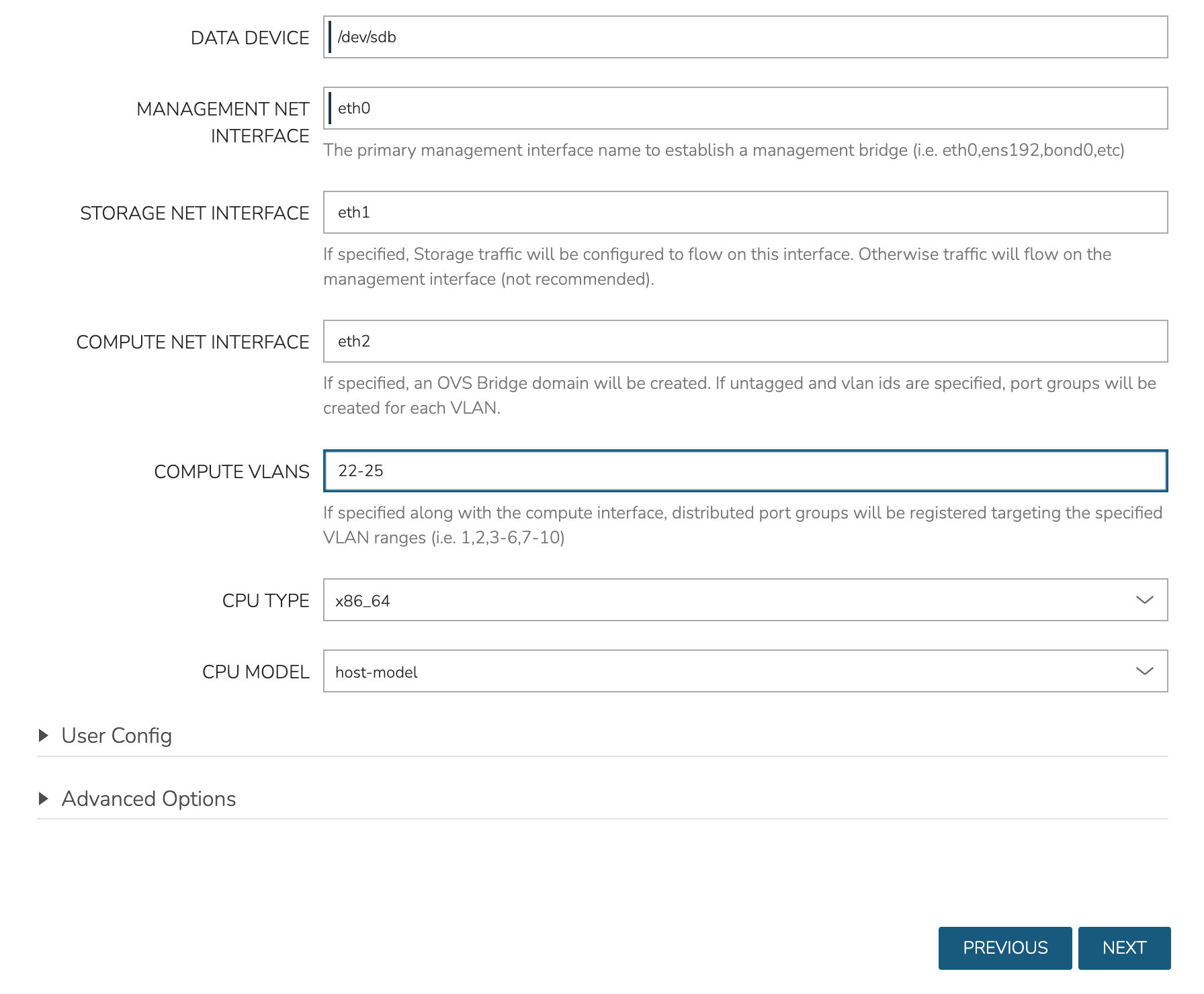
In the next part of the modal, you’ll configure the storage devices and network interfaces. When Ceph initializes, it needs to be pointed to an initial data device. Configure this in the DATA DEVICE field. At this time, only one device may be given but in the near future, an update will allow for multiple devices to be configured which would be added to the total Ceph storage as one large volume. Find your disk name, if needed, with the lsblk command. In my case, the target device is located at /dev/sdb.
Though not strictly required, it’s recommended to have separate network interfaces to handle cluster management, storage traffic, and compute. In this example case, eth0 is configured as the MANAGEMENT NET INTERFACE which handles communication between the cluster hosts. eth1 is configured as the STORAGE NET INTERFACE and eth2 is configured as the COMPUTE NET INTERFACE. The COMPUTE VLANS field can take a single value (ex. 1) or a range of values (ex. 22-25). This will create OVS port group(s) selectable as networks when provisioning workloads to the cluster. If needed, you can find your network interface names with the ip a command.
Finally, only one CPU TYPE is currently supported (x86_64) though this may change in the future. For CPU MODEL configuration, we surface the entire database of model configurations from libvirt. If unsure or if you don’t know of a specific reason to choose one or the other, select host-model which is the default option.
At this point we’ve kicked off the process for configuring the cluster nodes. Drill into the Cluster detail page and click on the History tab. Here we can monitor the progress of configuring the cluster. HPE Morpheus Enterprise will run scripts to install KVM, install Ceph, install OVS, and to prepare the cluster. In just a short time, the cluster provisioning should complete and the cluster will be ready to deploy workloads.
Provisioning a Workload
At this point, the cluster is ready for workloads to be provisioned to it. The system default Ubuntu Instance Type contains a compatible Layout for HVM deployment. Add an Instance from the Instances list page (Provisioning > Instances). After selecting the Instance Type, choose a Group that allows for selection of the HPE Morpheus Enterprise-type Cloud containing the HVM cluster.
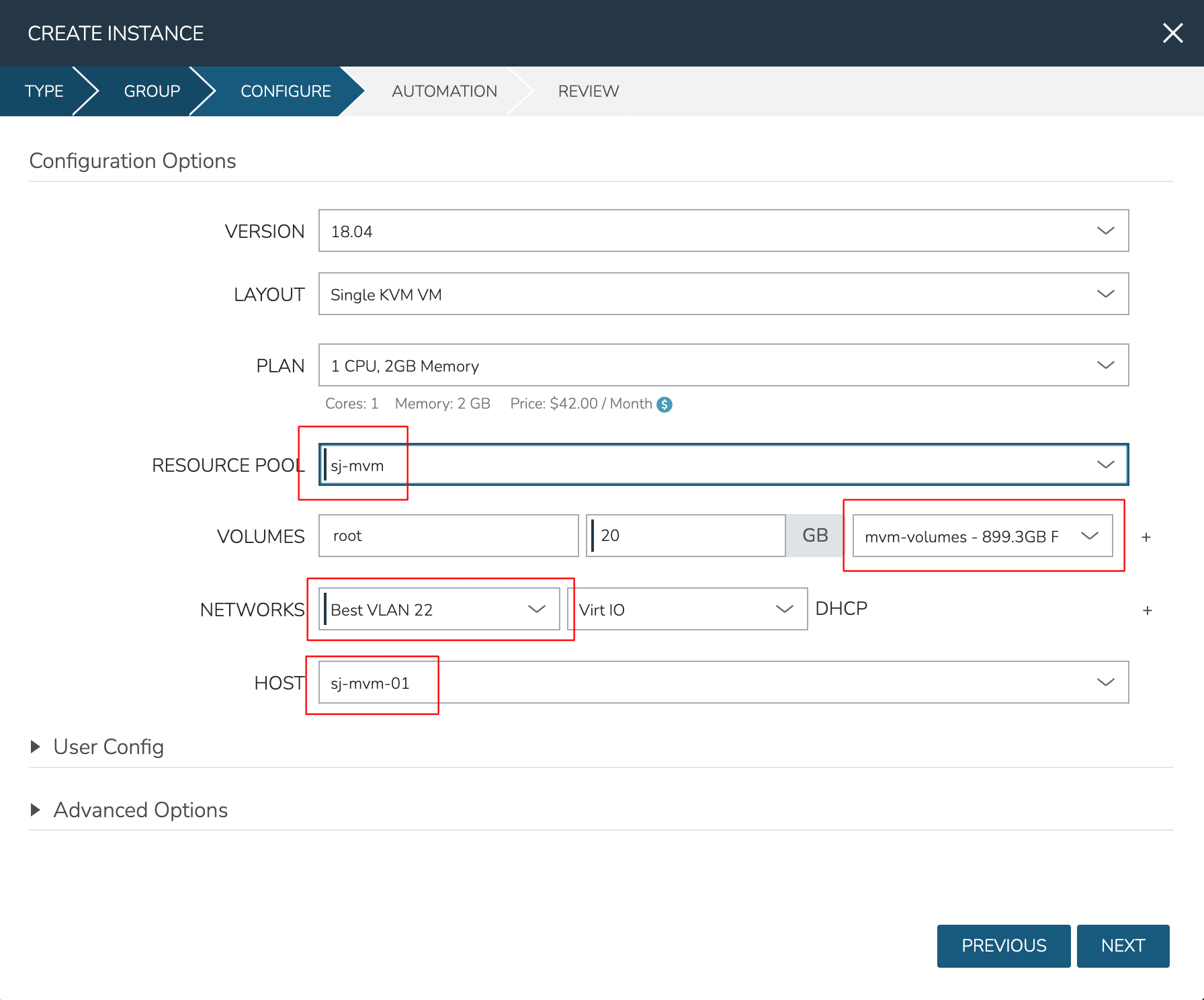
After moving to the next tab, select a Plan based on resource needs. From the RESOURCE POOL field, select the desired HVM cluster. When configuring VOLUMES for the new workload, note that space can be claimed from the Ceph volume. Within NETWORKS, we can add the new workload to one of the VLANS set up as part of cluster creation. Finally, note that we can choose the HOST the workload should run on.
Review and complete the provisioning wizard. After a short time, the workload should be up and running. With a workload now running on the cluster, we can take a look at some of the monitoring, migration, failover, and other actions we can take for workloads running on HVM clusters.
Note
HVM Clusters support CPU pinning (tying specific vCPUs of running VMs to specific physical CPU cores). Currently, this must be done manually by accessing the appropriate HVM Host and issuing virsh commands or editing XML. Adding UI tools to view and control CPU pinning is on the product roadmap to be added in the near future. Despite the requirement to edit CPU pinning manually, this is a supported action for workloads running on HVM Clusters.
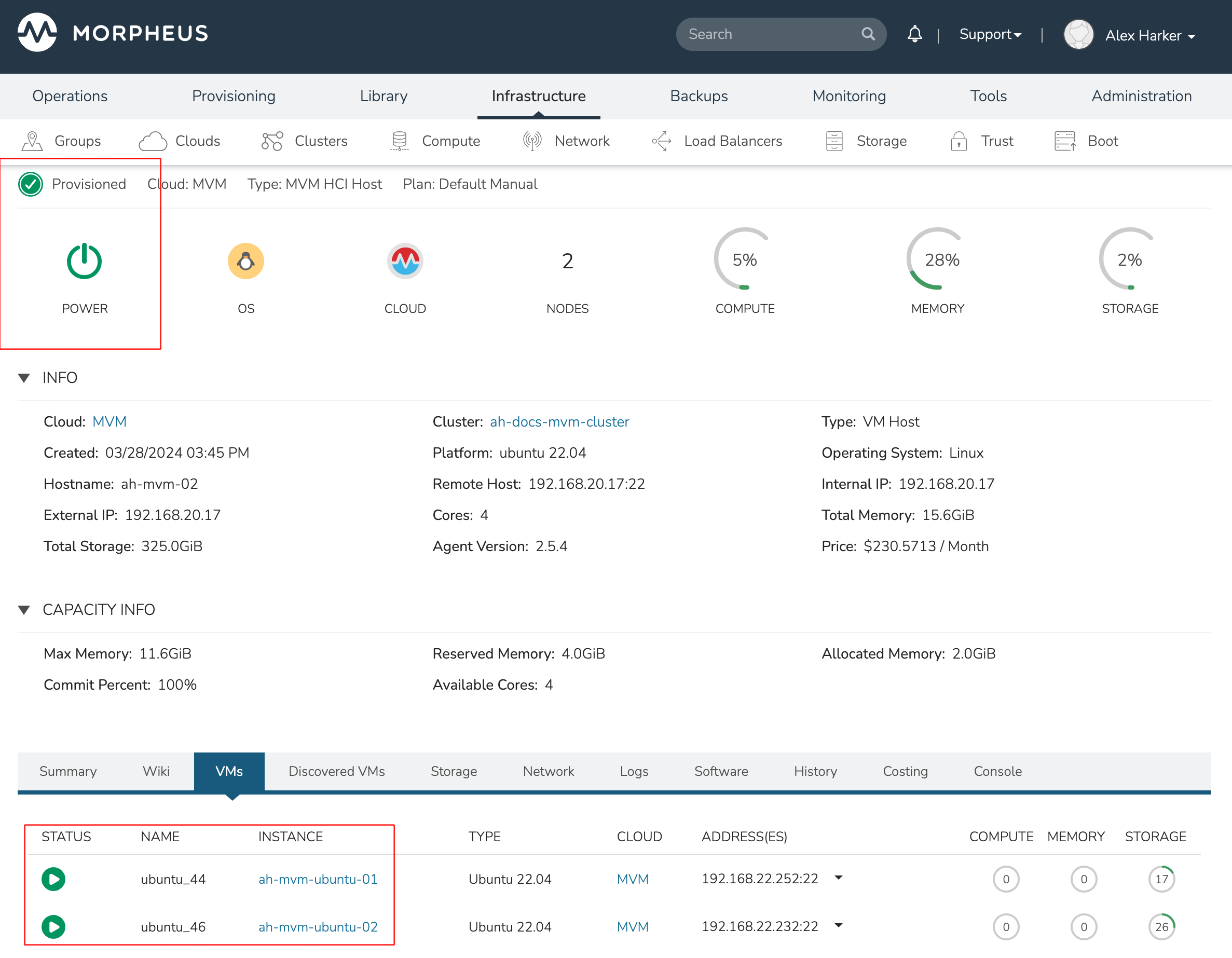
Monitoring the Cluster
With the server provisioned and a workload running, take a look at the monitoring and actions capabilities on the cluster detail page (Infrastructure > Clusters, then click on the new HVM cluster). View cluster performance and resource usage (Summary and Monitoring tabs), drill into individual hosts (Hosts tab), see individual workloads (VMs tab), and more.
Moving Workloads Between Hosts
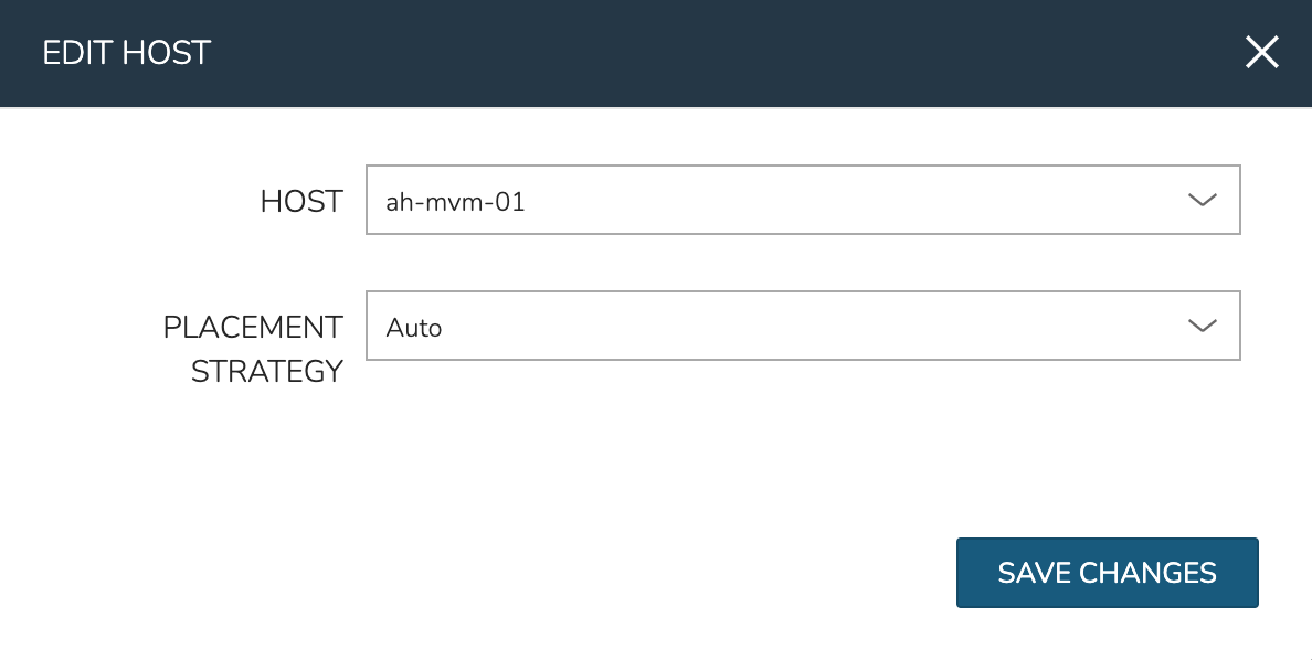
To manually move workloads between hosts, drill into the detail page for the VM (from the VMs tab of the cluster detail page). Click ACTIONS and select “Manage Placement”. Choose a different host and select from the following placement strategies:
Auto: Manages VM placement based on load
Failover: Moves VMs only when failover is necessary
Pinned: Will not move this workload from the selected host
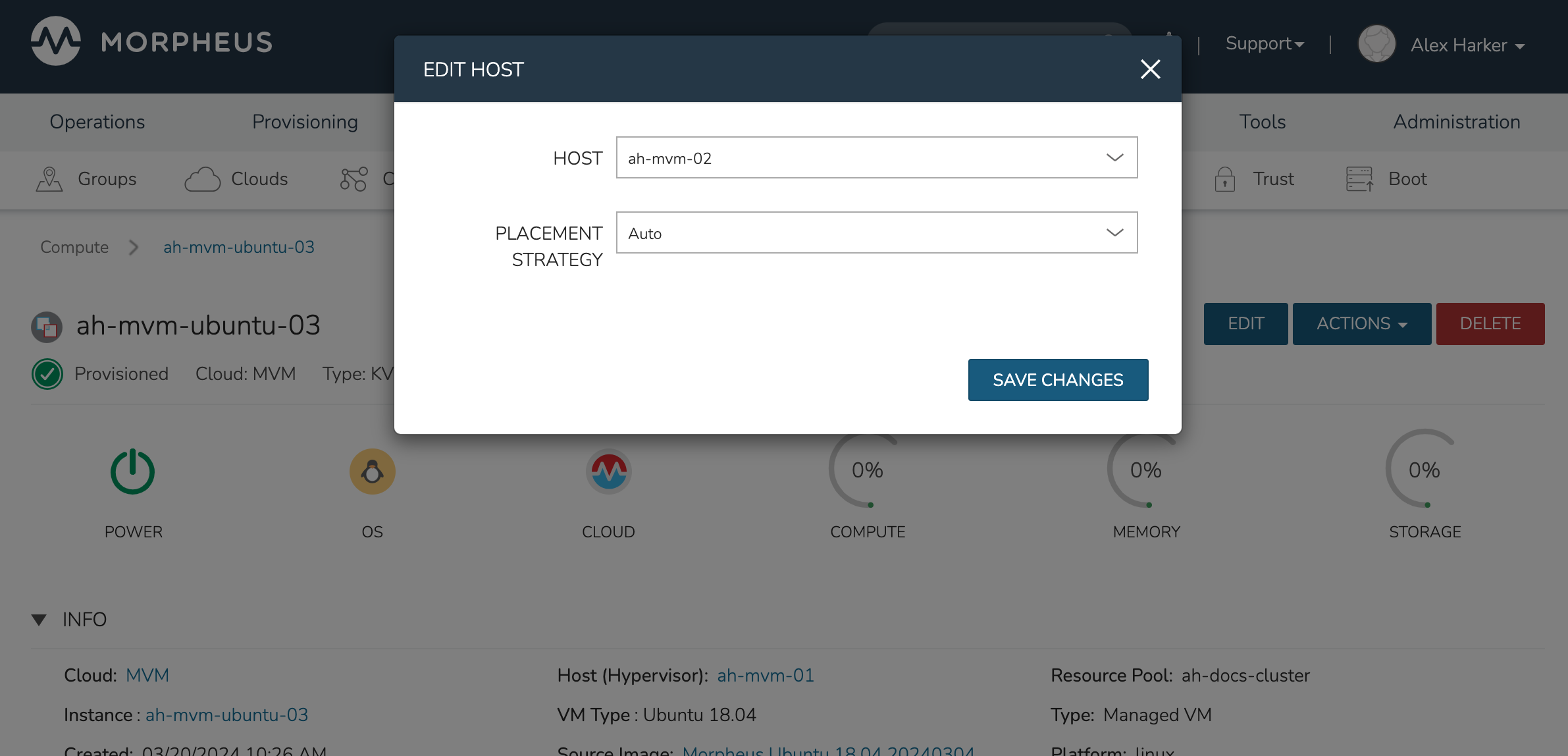
Within a short time, the workload is moved to the new host.
Adding hosts
The process of adding hosts to a pre-existing cluster is very similar to the process of provisioning the cluster initially. The requirements for the new worker node will be identical to the nodes initially added when the cluster was first provisioned. See the earlier sections in this guide for additional details on configuring the worker nodes.
To add the host, begin from the HVM Cluster detail page (selected from the list at Infrastructure > Clusters). From the Cluster detail page, click ACTIONS and select “Add Worker”. Configurations required are the same as those given when the cluster was first created. Refer to the section above on “Provisioning the Cluster” for a detailed description of each configuration.
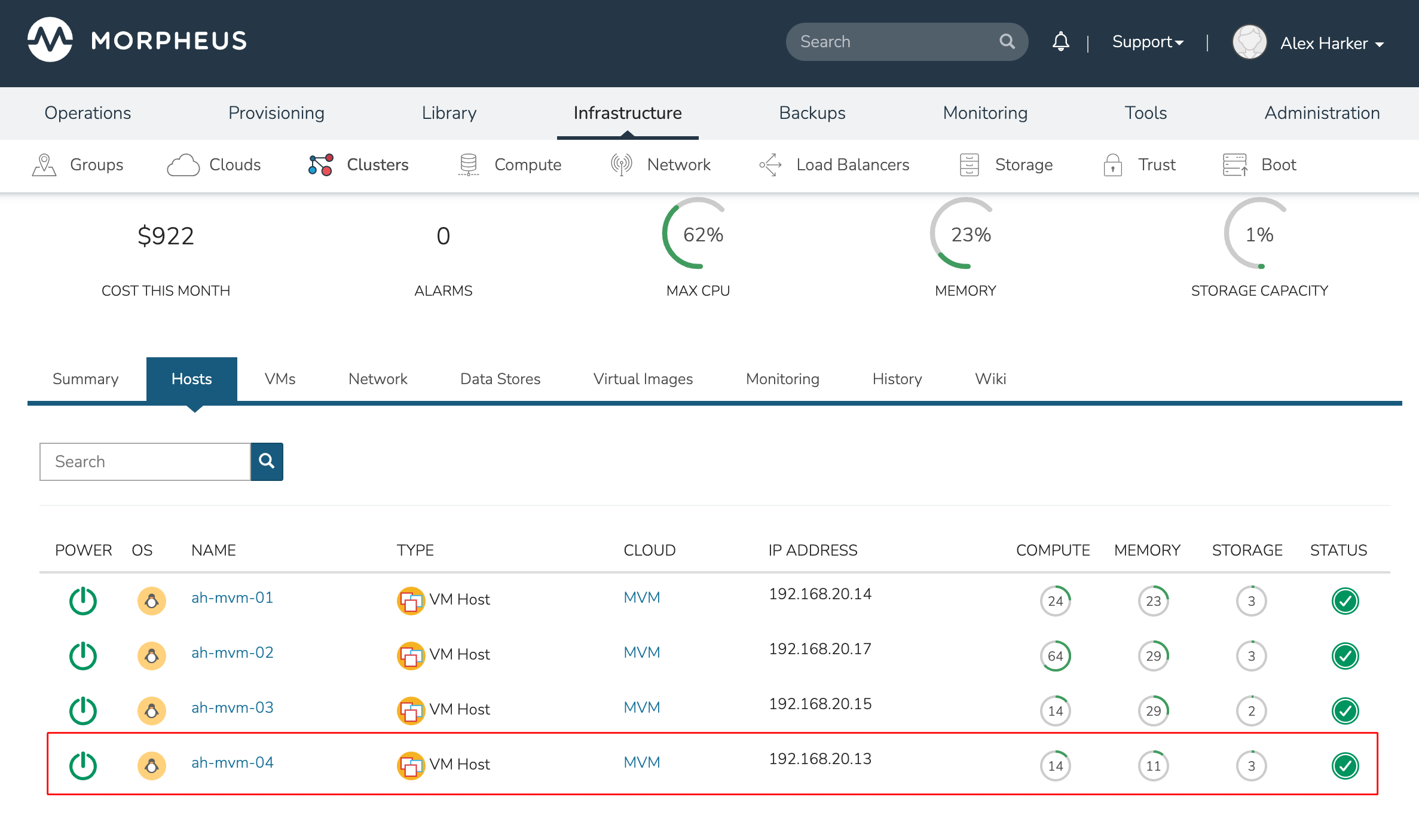
Once HPE Morpheus Enterprise has completed its configuration scripts and joined the new worker node to the cluster, it will appear in a ready state within the Hosts tab of the Cluster detail page. When provisioning workloads to this Cluster in the future, the new node will be selectable as a target host for new Instances. It will also be an available target for managing placement of existing VMs running on the cluster.
Note
It’s useful to confirm all scripts related to creating the new host and joining the new host to the cluster completed successfully. To confirm, navigate to the detail page for the new host (Infrastructure > Clusters > Selected Cluster > Hosts Tab > Selected Host) and click on the History tab. Confirm all scripts, even those run on the pre-existing hosts, completed successfully as it’s possible the new host was added successfully (green status) but failed in joining the cluster. When such a situation occurs it may appear adding the new host was successful though it will not be possible to provision workloads onto it due to not joining the cluster successfully.
Maintenance Mode
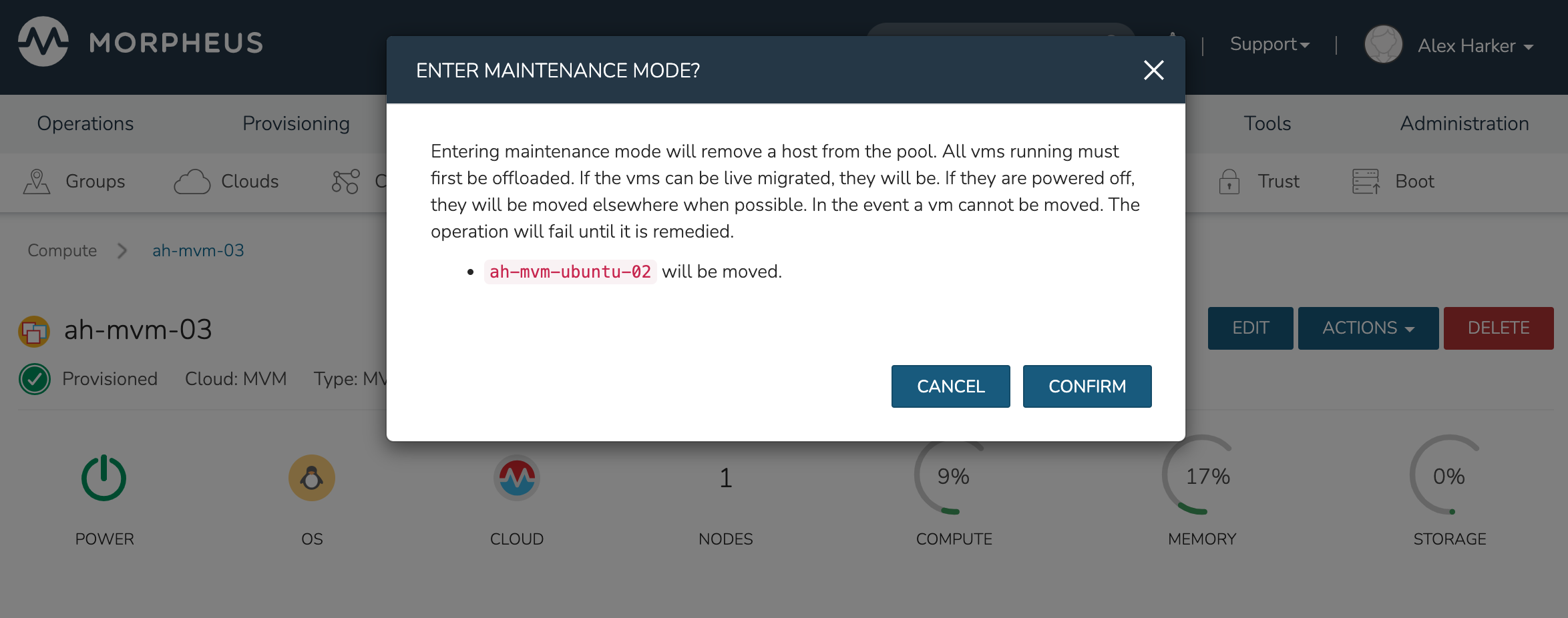
HVM cluster hosts can be easily taken out of service for maintenance when needed. From the host detail page, click ACTIONS and then click “Enter Maintenance.” When entering maintenance mode, the host will be removed from the pool. Live VMs that can be migrated will be moved to new hosts. VMs that are powered off will also be moved when possible. When a live VM cannot be moved (such as if it’s “pinned” to the host), the host will not go into maintenance mode until that situation is cleared. You could manually move a VM to a new host or you could power it down if it’s non-essential. After taking that action, attempt to put the host into maintenance mode once again. HPE Morpheus Enterprise UI provides a helpful dialog which shows you which VMs live on the host are to be moved as the host goes into maintenance mode. When maintenance has finished, go back to the ACTIONS menu and select “Leave Maintenance.”
Failover
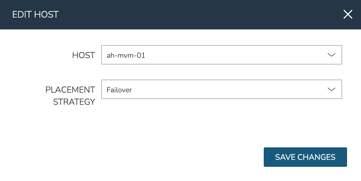
HVM supports automatic failover of running workloads in the event of the loss of a host. Administrators can control the failover behavior through the “Manage Placement” action on any running VM. From the VM detail page, click ACTIONS and select “Manage Placement”. Any VM with a placement strategy of “Auto” or “Failover” will be eligible for an automatic move in the event its host is lost. When the loss of a host does occur, the workload will be up and running from a different cluster host within just a short time if it’s configured to be moved during an automatic failover event. Any VMs pinned to a lost host will not be moved and will not be accessible if the host is lost. When the host is restored, those VMs will be in a stopped state and may be restarted if needed.
This three-node cluster has three VMs running on the first host:
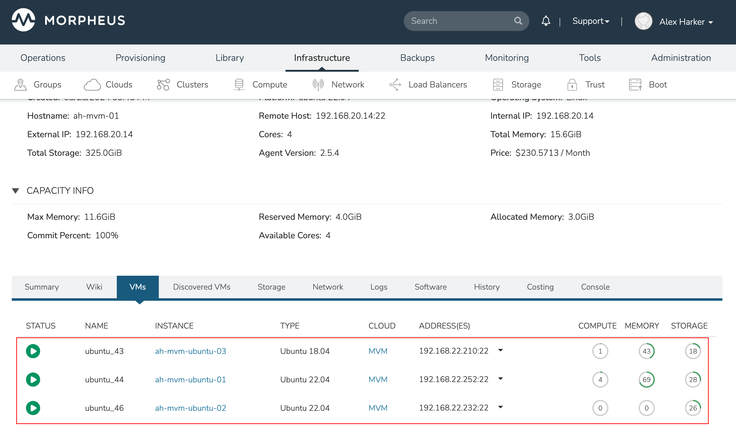
Each of these VMs is configured for a different failover strategy. When the host is lost, we should expect to see the first two VMs moved to an available host (since they have the “Auto” and “Failover” placement strategies, respectively). We should not see the third VM moved.

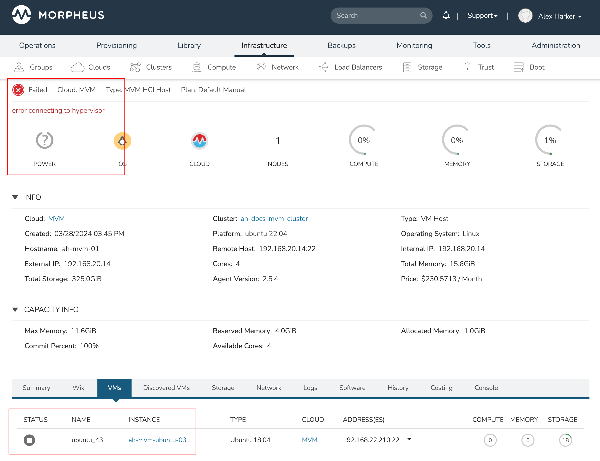
After loss of the host these three VMs were running on, we can see the lost host still has one associated VM in a stopped state. The other two VMs are running on a second host which is still available.
When the lost host returns, the moved VMs will come back to their original host. The third VM is associated with this host as well and is in a stopped state until it is manually restarted.
Adding an NFS Datastore
Existing NFS shares can be used with HPE Morpheus Enterprise HVM clusters for virtual machine storage. These are added and viewed from the Storage tab of the HVM cluster detail page and, once added and active, become selectable as targets for virtual machine storage.
Note
Ensure NFS is properly configured to allow all of the HVM hosts to access the shared directory, including permissions to read and write. For backup purposes, it’s also helpful to give HPE Morpheus Enterprise access to NFS.
Start by navigating to the Storage tab of the HVM cluster detail page. Make sure the Data Stores subtab is also selected. Here you will see a list of existing datastores with some additional information, such as type, capacity, and status. Click ADD. Enter the NAME for the datastore in HPE Morpheus Enterprise and select the TYPE as NFS Pool. Note that the datastore name cannot be changed once it has been created. This will update the available fields to include the additional fields needed to integrate the NFS server. Enter the SOURCE HOST which is the hostname or the IP address of the NFS server. Finally, enter the SOURCE DIRECTORY which is the directory path of the NFS share. Click SAVE.
Once the modal is saved, it will take a few minutes to initialize the new datastore and show a successful online status in HPE Morpheus Enterprise. Once this initialization process is completed, the datastore can now be used as VM storage for cluster.
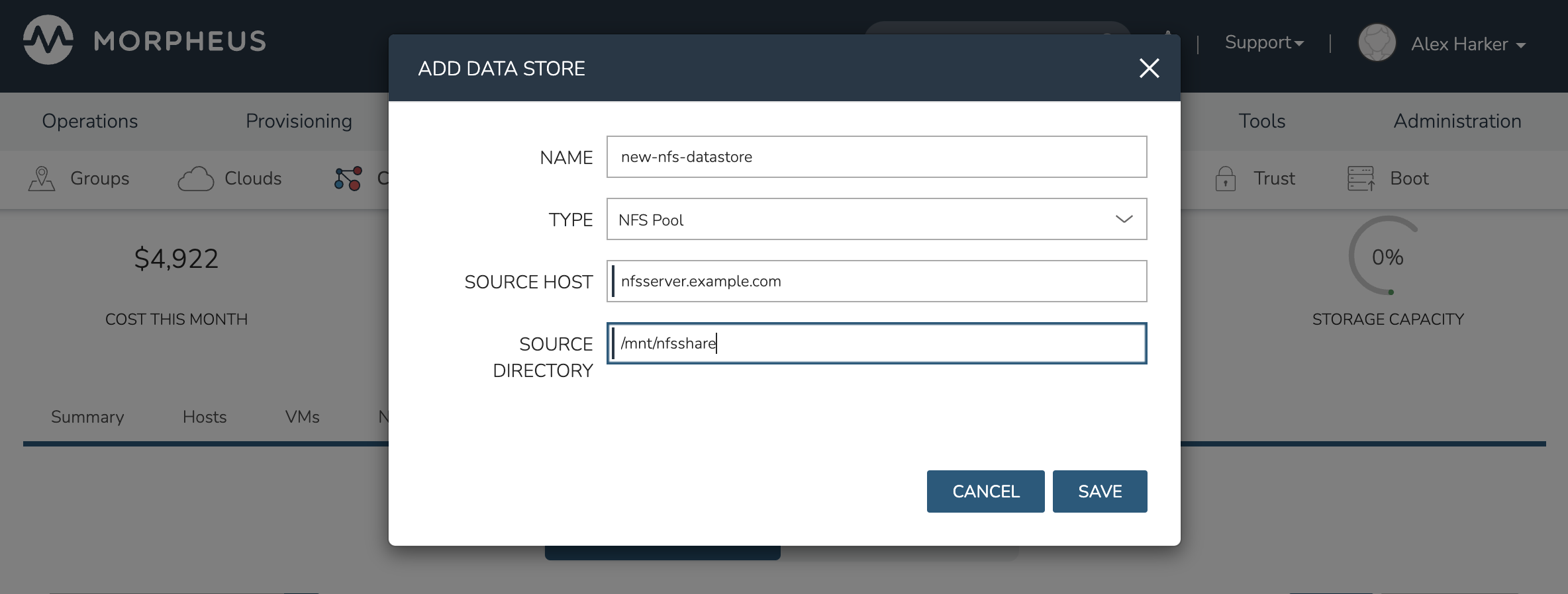
Image Prep (Windows)
This section will go through the steps to prepare a Windows image which can be successfully provisioned to HVM clusters. Additionally, this image can serve as a template from which additional images and HPE Morpheus Enterprise Library items can be built. In this example case, we’ll start from downloading a Windows Server 2019 ISO directly from the Microsoft download center and go all the way through to creating a new Instance Type in HPE Morpheus Enterprise that users can provision on-demand.
With the Windows ISO already downloaded, begin by uploading the ISO as a Virtual Image in HPE Morpheus Enterprise. Virtual Images are added in Library > Virtual Images. Click + ADD and then choose “ISO.” Before adding the file itself, set the following configurations on the Virtual Image:
NAME: A name for the Virtual Image in HPE Morpheus Enterprise, such as “Windows Server 2019 ISO”
OPERATING SYSTEM: “windows server 2019”
MINIMUM MEMORY: Filters out Service Plans at provision time which do not meet the minimum value. For this image type, I’ve set 4 GB
In addition to the above, there are a number of checkbox configurations here (many of them are in the expandable “Advanced” section), some of which are checked by default. They should all be unchecked except for “VIRTIO DRIVERS LOADED?” within the “Advanced” expandable section.
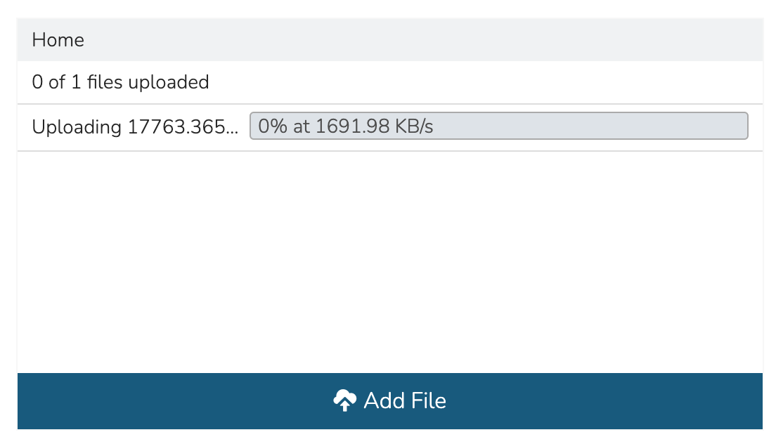
With the configurations set, it’s time to upload the ISO to HPE Morpheus Enterprise. Keep in mind that if you do not specify a bucket in which the file should be uploaded, it will be uploaded to the appliance itself. If you choose to do this, be sure you have enough space to store the images you need. Within the UPLOAD VIRTUAL IMAGE modal is a large dropzone labeled “Drop Files Here.” You can drag and drop the ISO file here or you can click the button labeled “Add File” and browse for it. A progress bar will appear, wait until the file is completely uploaded before you save and dismiss the modal. After the file has completely uploaded, click SAVE CHANGES.
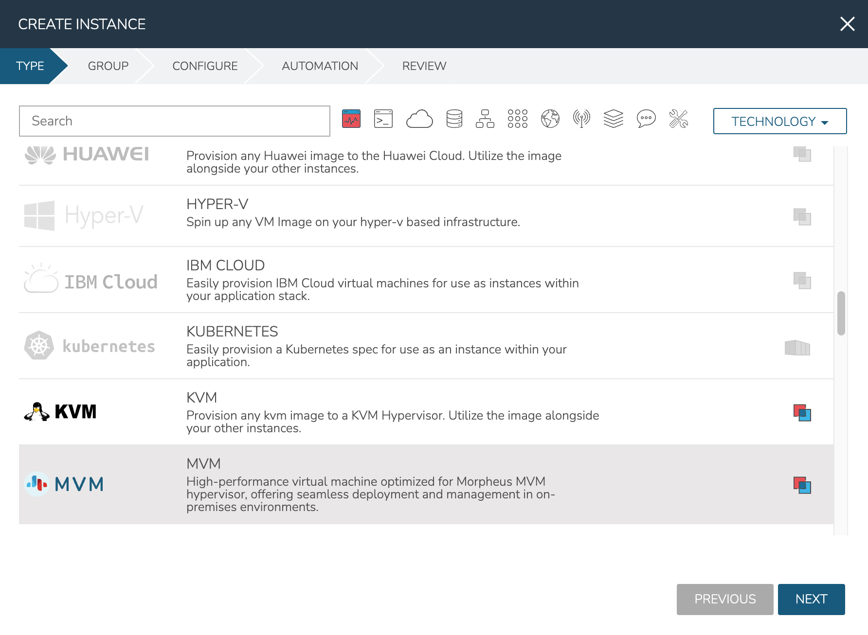
Next, we’ll provision a VM from the ISO using the built-in HVM Instance Type. Once running, we will configure the VM to any specific requirements and convert it to a template. Navigate to Provisioning > Instances and click + ADD. On the TYPE tab of the Instance provisioning wizard, we select the Instance Type to provision. In this case, select “HVM” and click NEXT.
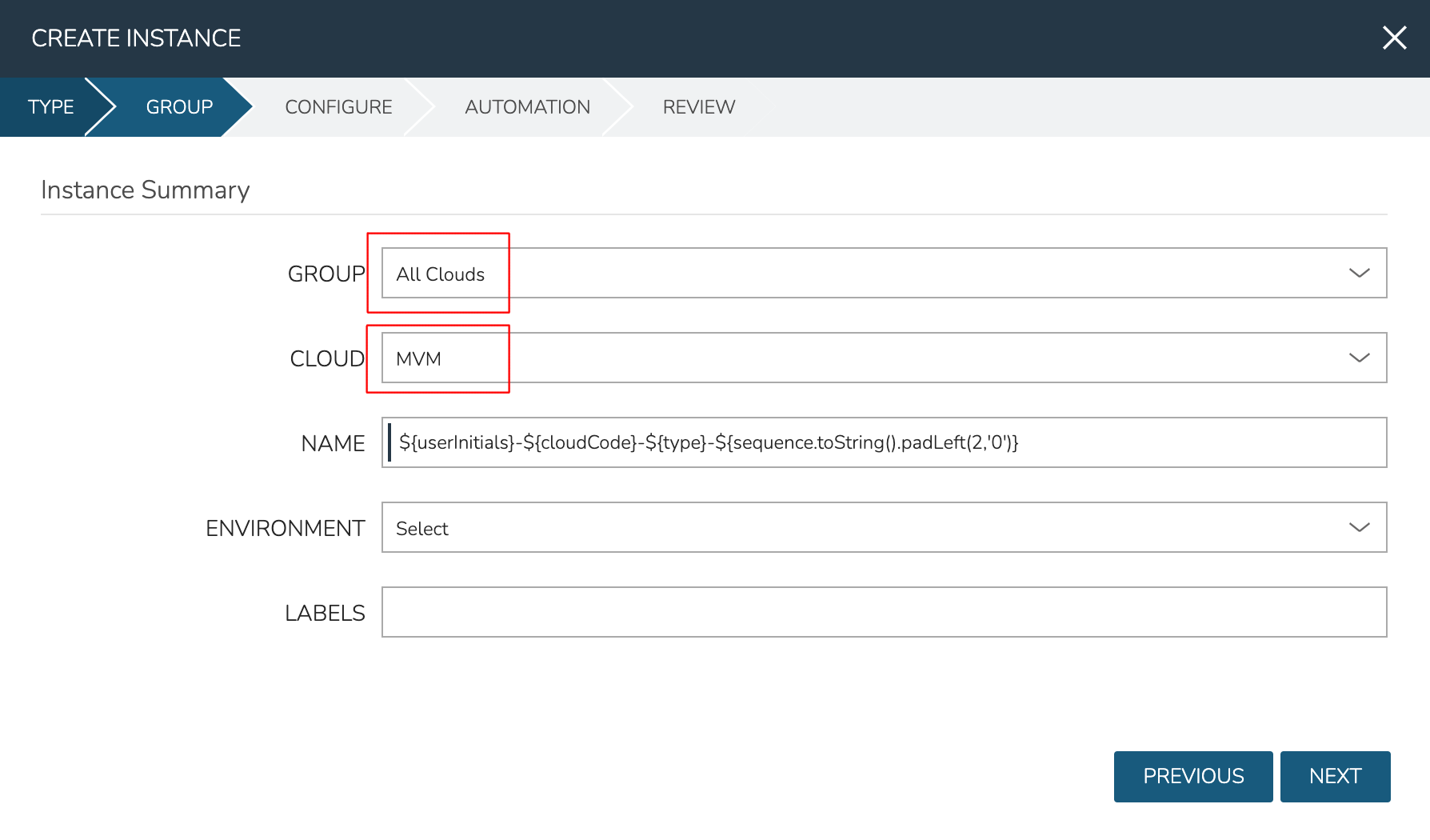
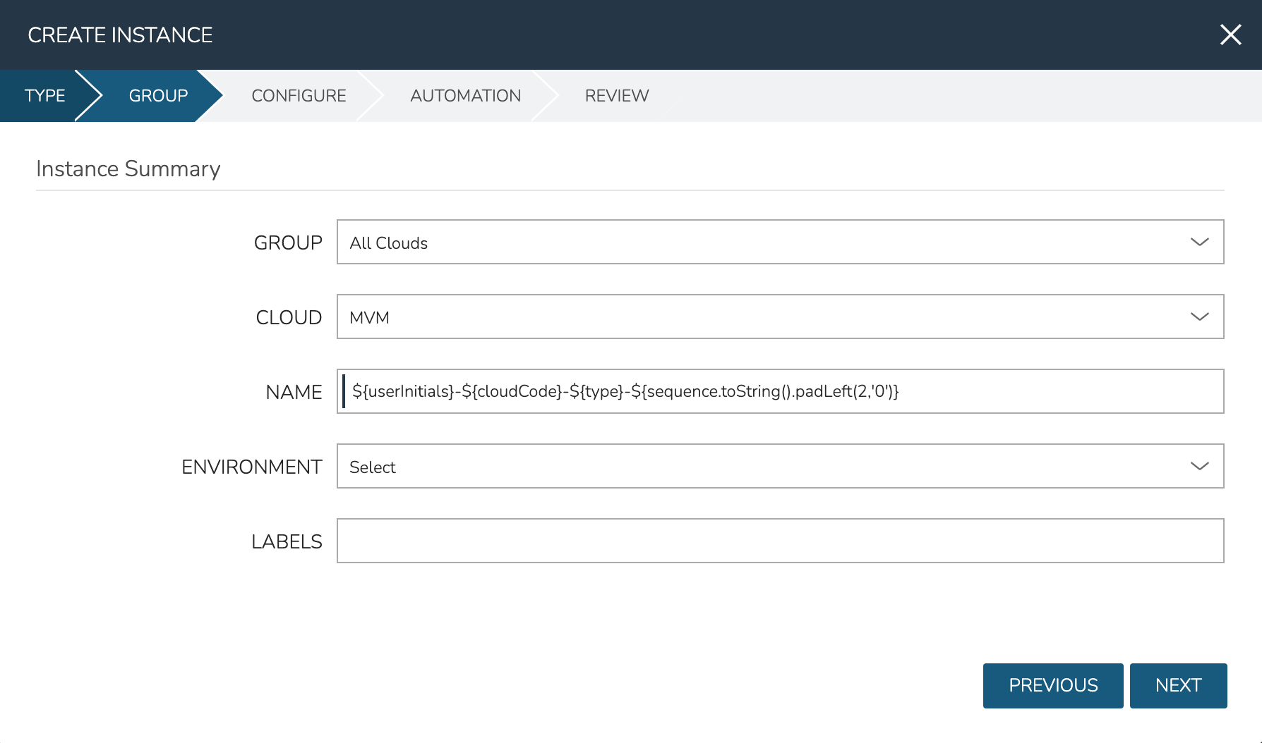
On the GROUP tab, select the Group and Cloud containing the target HVM Cluster and provide a name for the new Instance. In my case, I have an automatic naming policy setting my Instance name, but depending on your appliance configuration you may need to enter a custom name. Click NEXT.
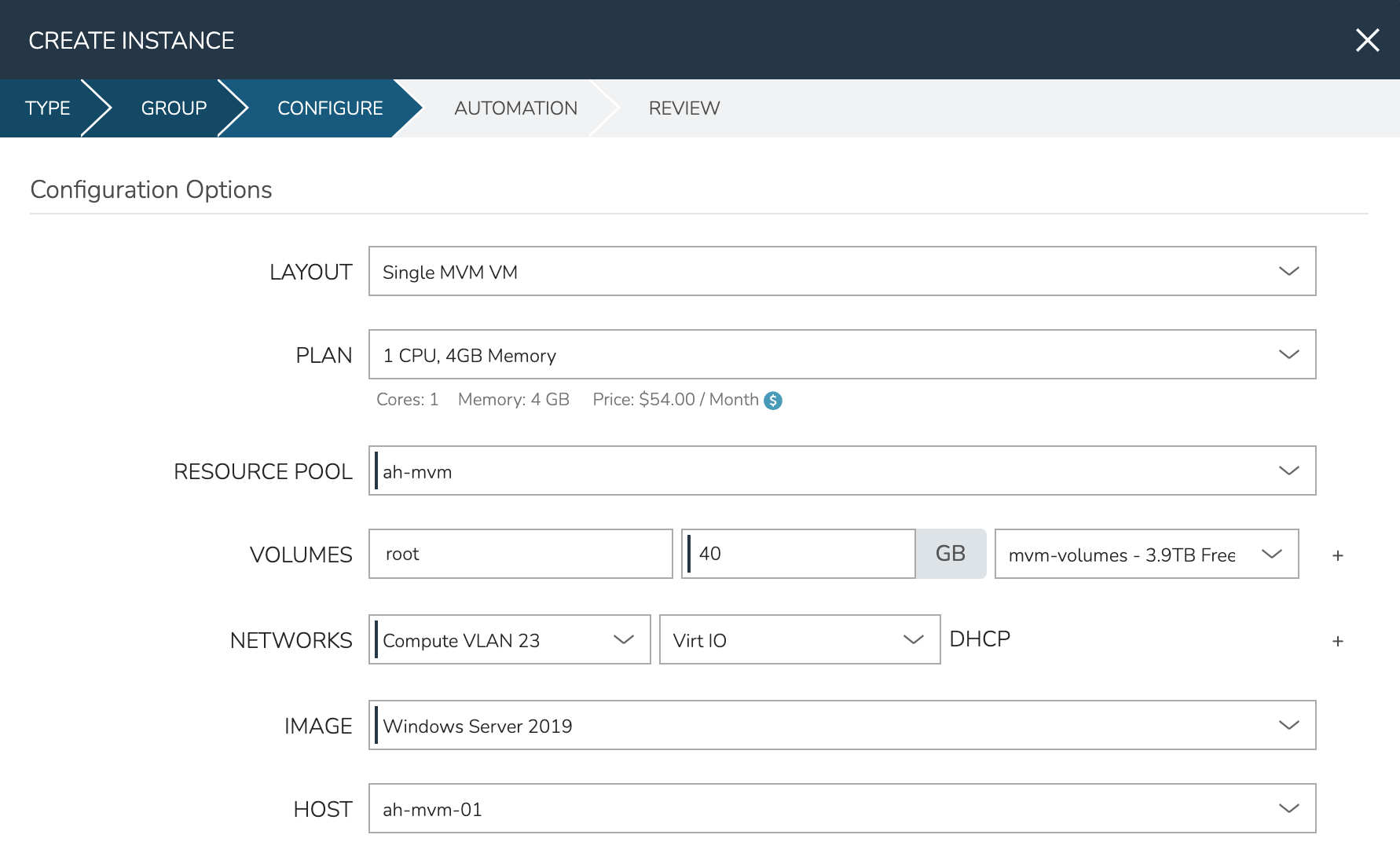
On the CONFIGURE tab, first select the IMAGE. Select the Windows server ISO that was uploaded in the previous step. Based on the minimum memory configuration that was set on the Virtual Image, Plans which are too small will be filtered out. Among compatible Plans, select one that meets your requirements. Next, set the RESOURCE POOL, which is the HVM cluster you’re targeting. Configure disks and disk sizes, as well as network details (this will vary based on HVM cluster configuration). Finally, select the HOST, which is the HVM host within the cluster that the new Instance should initially be provisioned onto.
As a final step, we need to also expand the “Advanced Options” section and make sure “ATTACH VIRTIO DRIVERS” is checked. This will attach an ISO containing the VirtIO drivers which we’ll use later. Click NEXT.
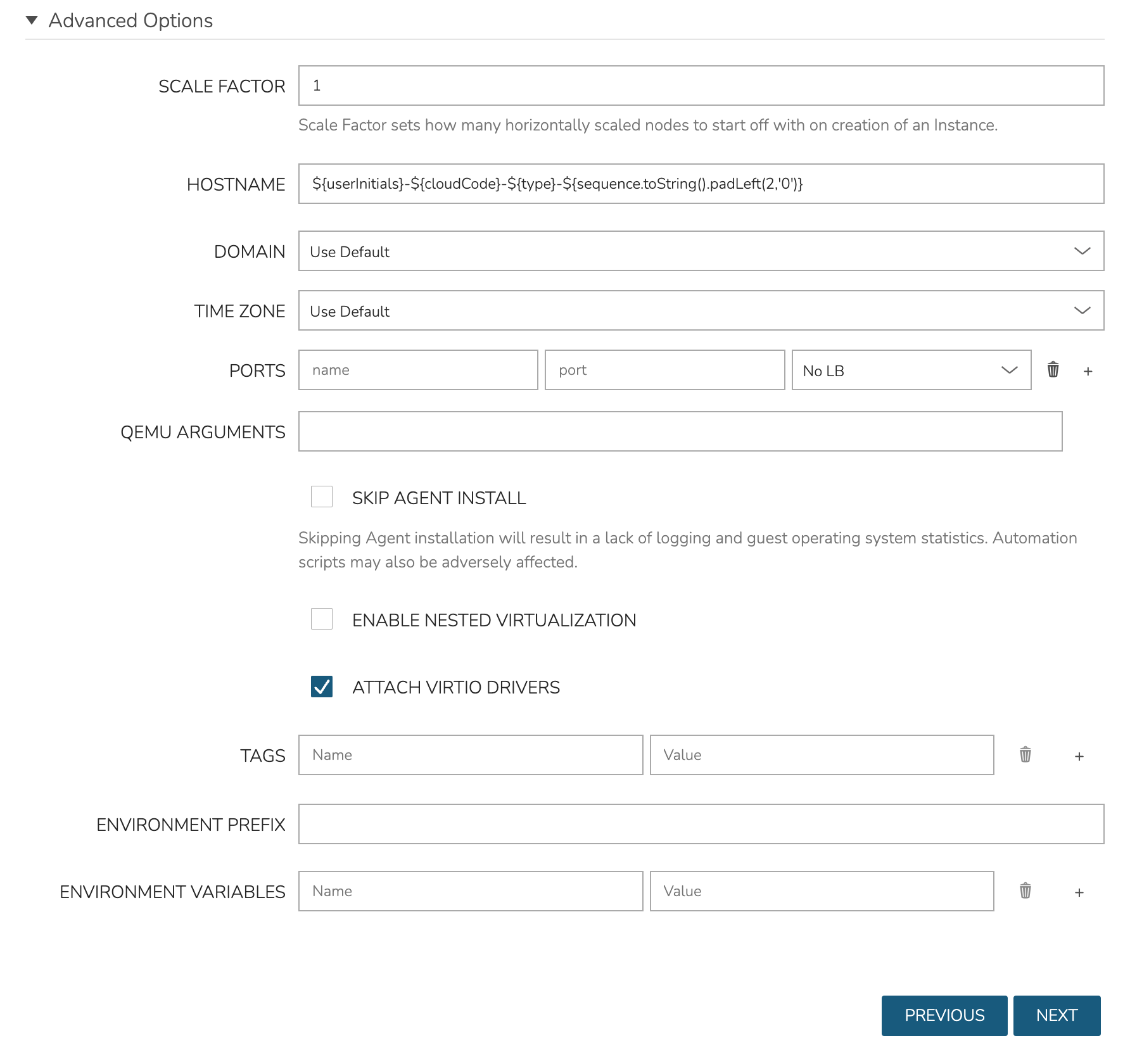
The final two tabs of the wizard, AUTOMATION and REVIEW, do not require any configuration changes though you may want to review the Instance settings on the final tab. When done, click COMPLETE.
Click on the newly provisioning Instance from the Instances list page. Since this image is being provisioned for the first time, the image must be uploaded to the HVM host. This can take a little bit of time but any future attempts to provision workloads from this image will skip this step. Wait for the Instance to fully complete and appear in a green “Ready” status.
Once the Instance has fully finished provisioning, launch a console session by clicking ACTIONS and then “Open Console.” This will open a new window with a console session into the VM.
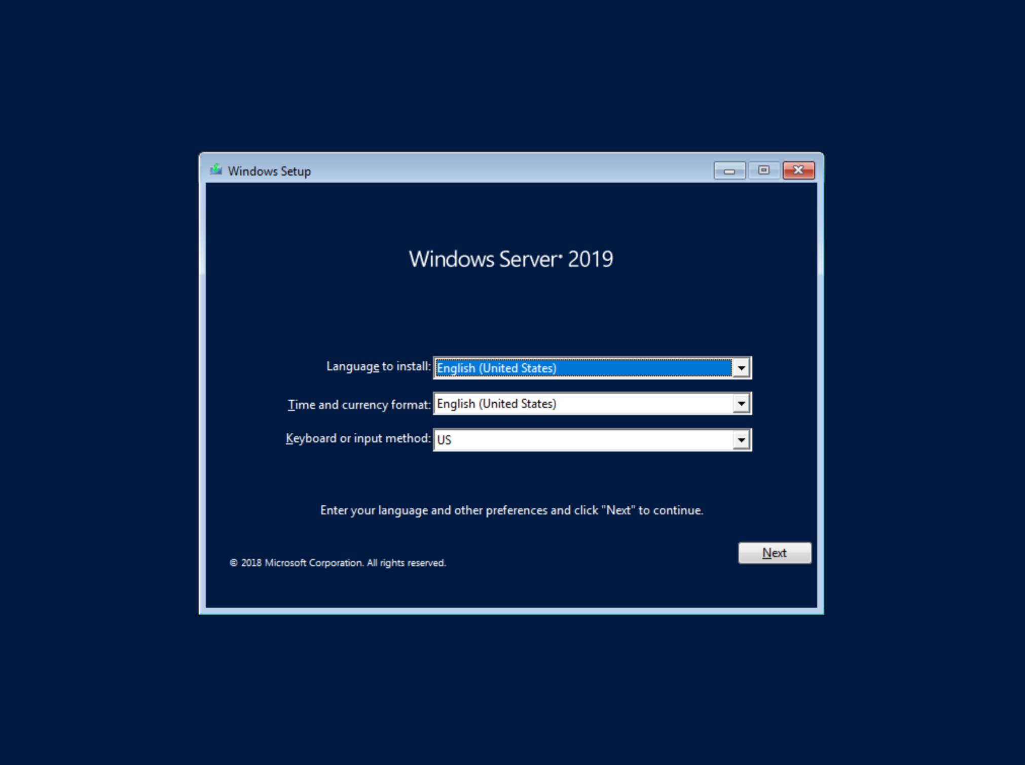
After selecting the language, click “Next.” On the following screen, click “Install Now.” This will begin the Windows setup process on our new VM. You’ll next select the operating system type you wish to install. For this example, I’m installing 2019 standard with desktop experience. Click “Next.”

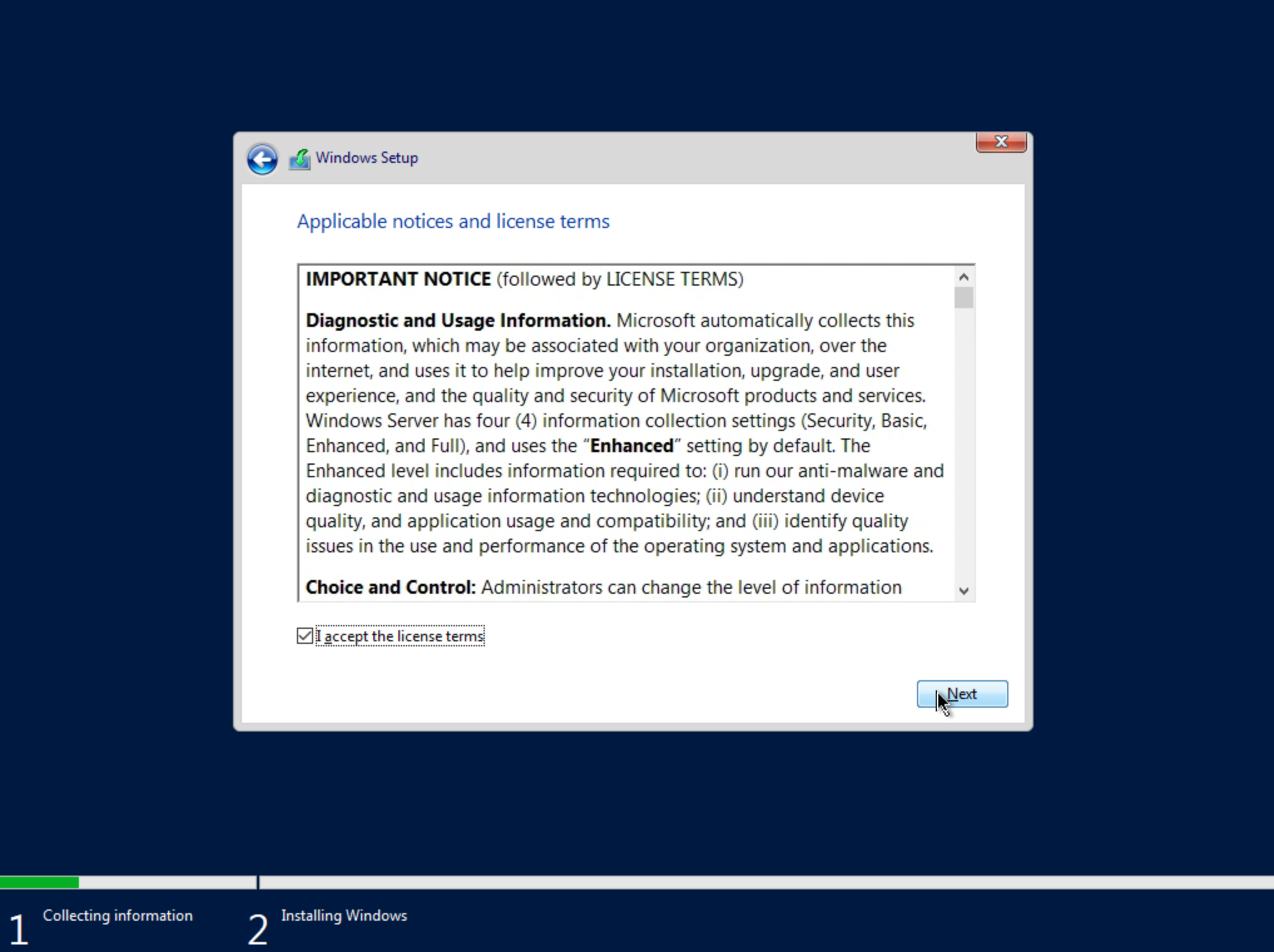
Accept the licensing terms and click “Next.”
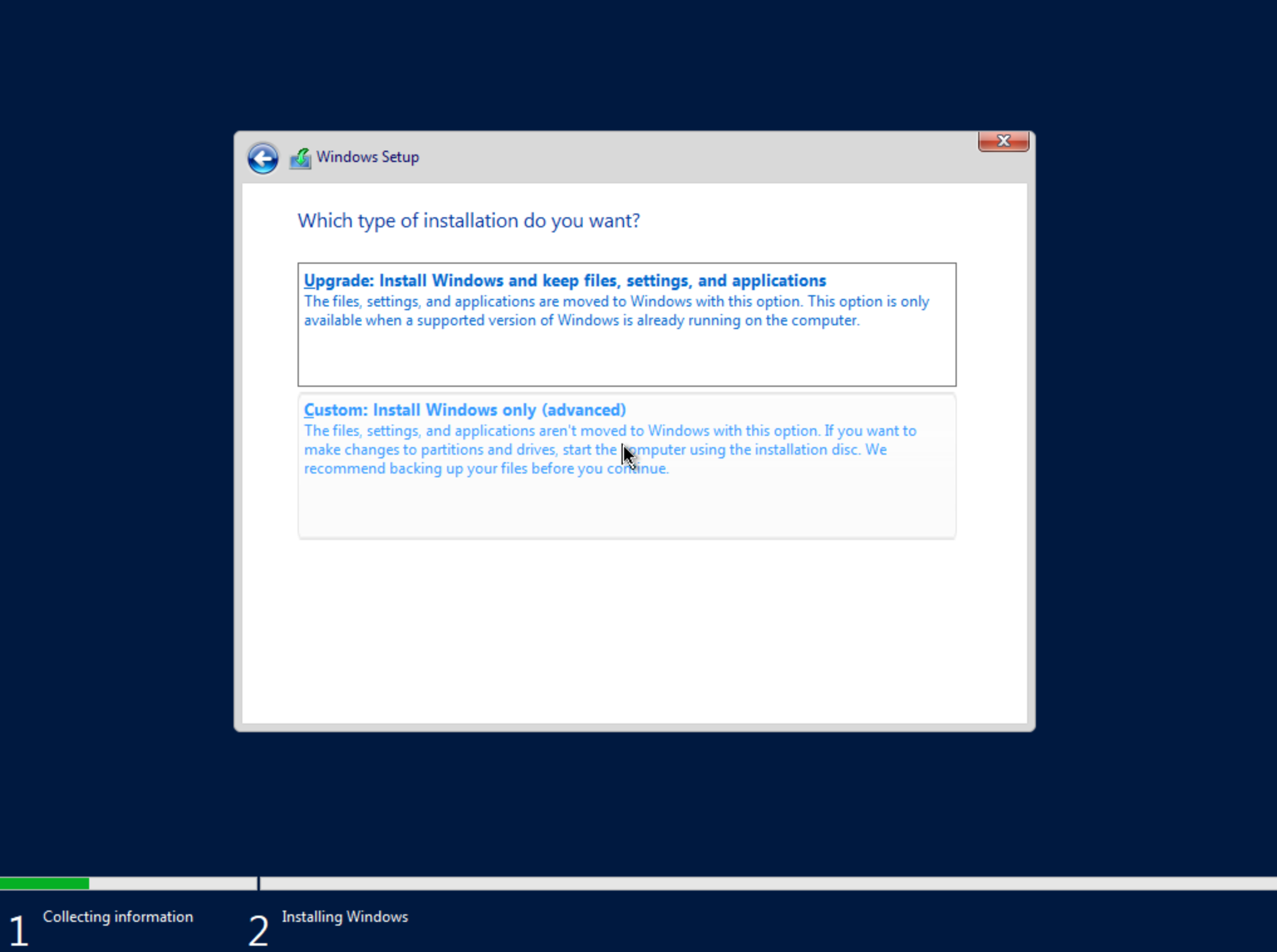
On the next screen, choose a custom install.
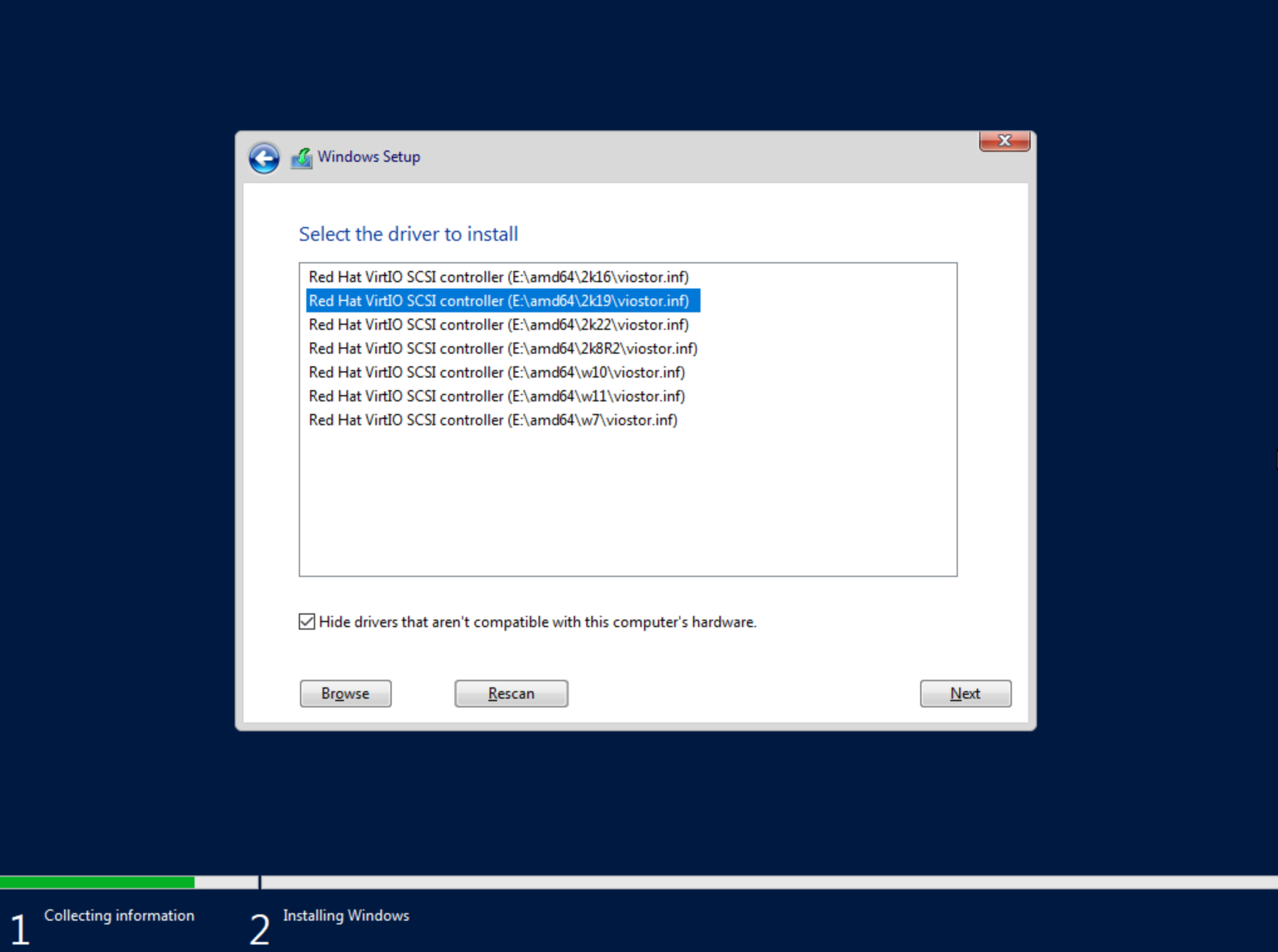
The next screen asks where Windows should be installed and may be empty. Click “Load Driver” to locate the mounted disk image containing the VirtIO drivers. The search should return a number of VirtIO SCSI controller packages for various Windows flavors. Select the proper package for the Windows version being installed. Click “Next.”
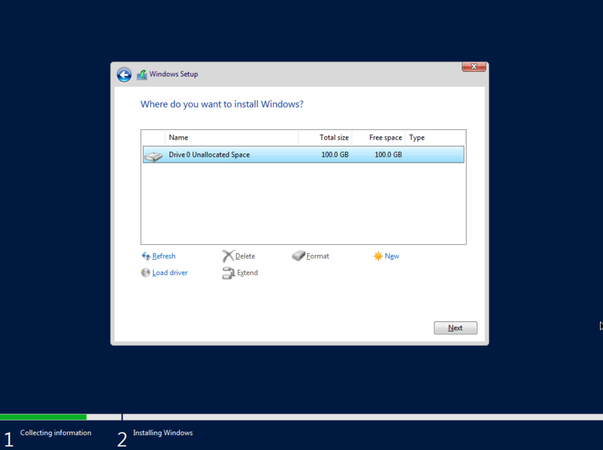
After a moment, we’re back at the screen asking where Windows should be installed. We should see the disk(s) of size and type selected at the time the VM was provisioned. Select the proper disk and click “Next.” The Windows installation will now begin. Once Windows has fully installed, proceed to the next step.
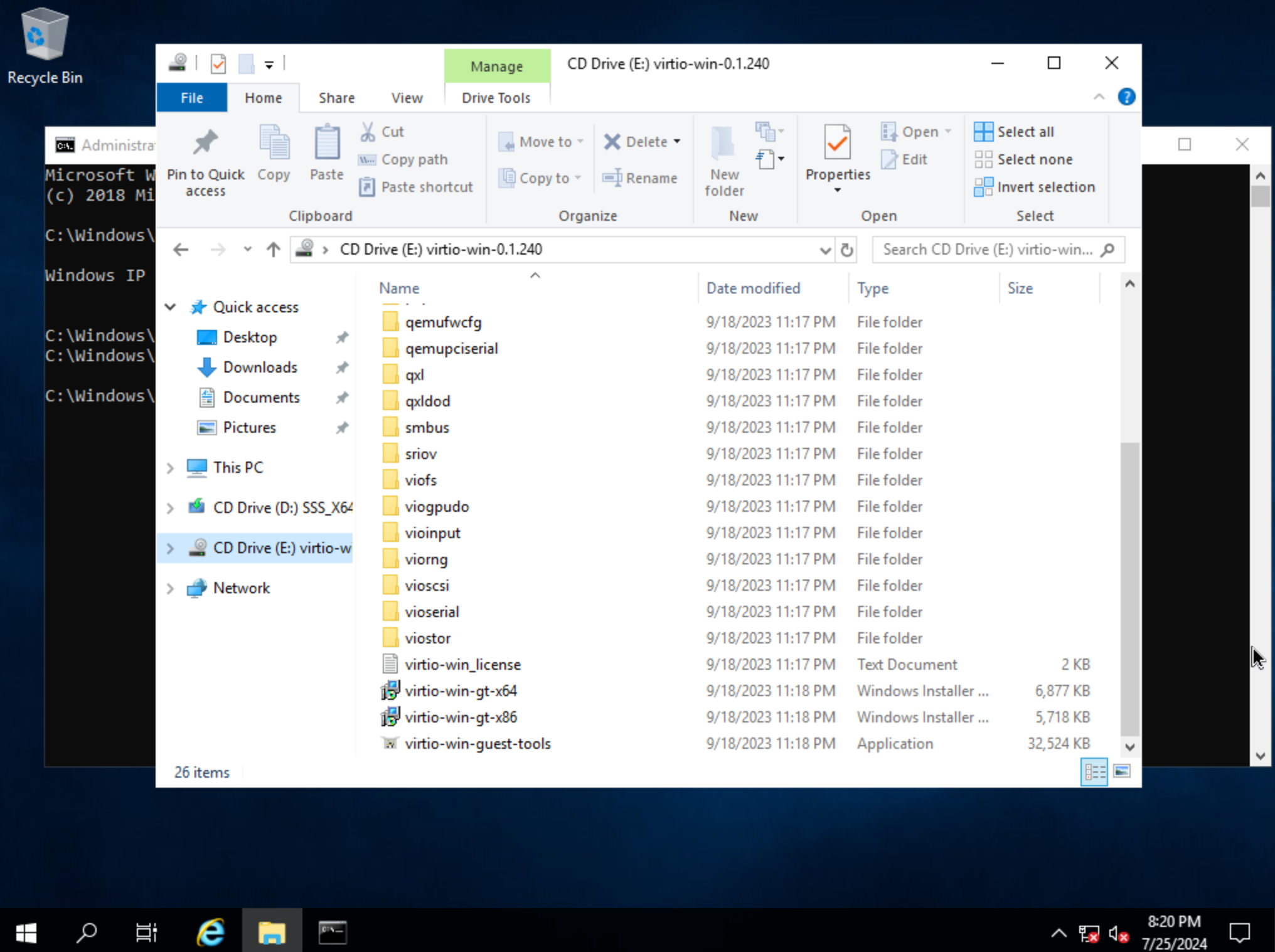
Following installation, Windows will restart and prompt for an Administrator user password. Set the password and log in as Administrator. Currently, there are no network interfaces configured. We need to install the VirtIO drivers to get this machine onto the network. We have a disk image mounted with the driver installer so we need to navigate to that drive and launch the installer. Open Windows Explorer and locate the drive in the side bar. In my case, it’s the E: drive. Right-click on virtio-win-guest-tools and select “Install.”
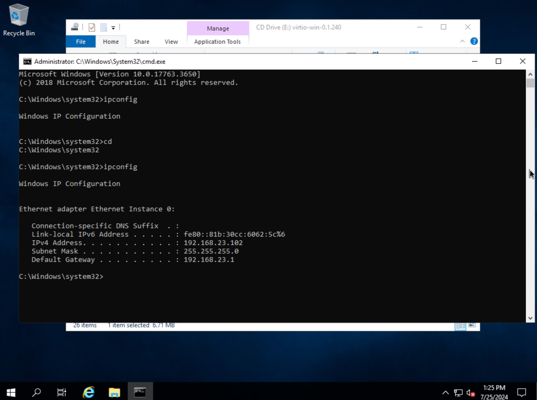
Step through the installer. Simply click “Next” or “Install” through each step, there are no configuration changes needed. Once the installer has completed, click “Finish.” You can confirm we now have a network interface by opening a Command Prompt session and using the ipconfig command. One network adapter should be listed.
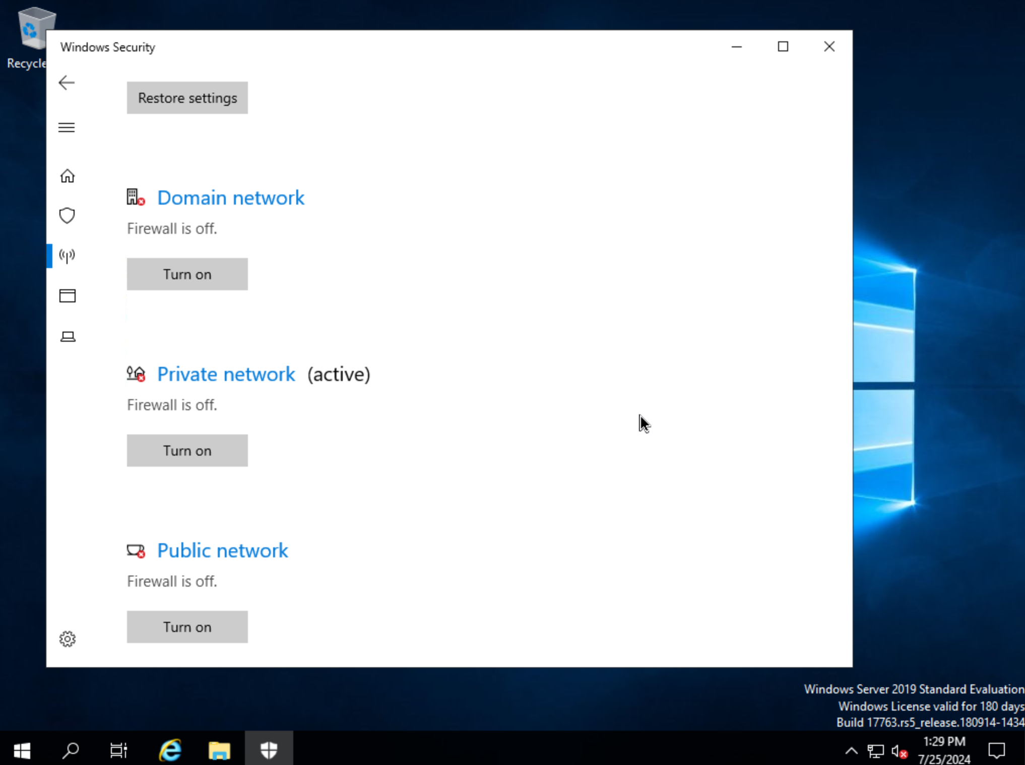
We can now eject the two virtual disks, drives D: and E: in my case. Then, launch Windows Security so we can disable firewalls. Turn off firewall for domain, private network, and public network.
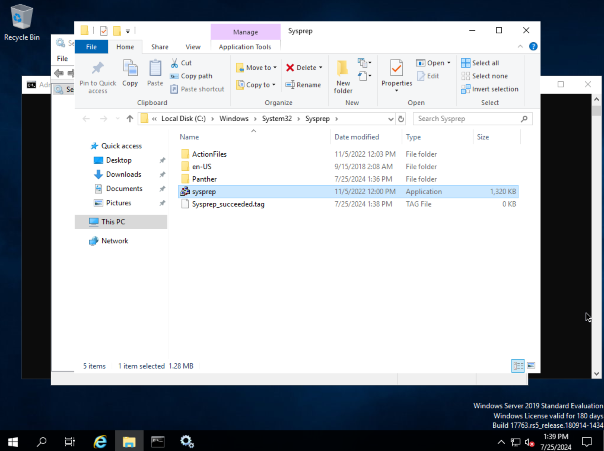
Next, back in Command Prompt, run winrm quickconfig to configure winrm. Within Services, ensure that winrm (Windows Remote Management) is set to automatic on startup. Right-click on the Start button and select Run. Enter “sysprep” and click OK. In the Windows Explorer window that appears, right-click on sysprep and click “Run as Administrator”. Under “Shutdown Options”, choose Quit and click OK. If this is set to shutdown, HPE Morpheus Enterprise will simply restart the VM. Once this is completed, a new file Sysprep_succeeded.tag appears in Windows Explorer.
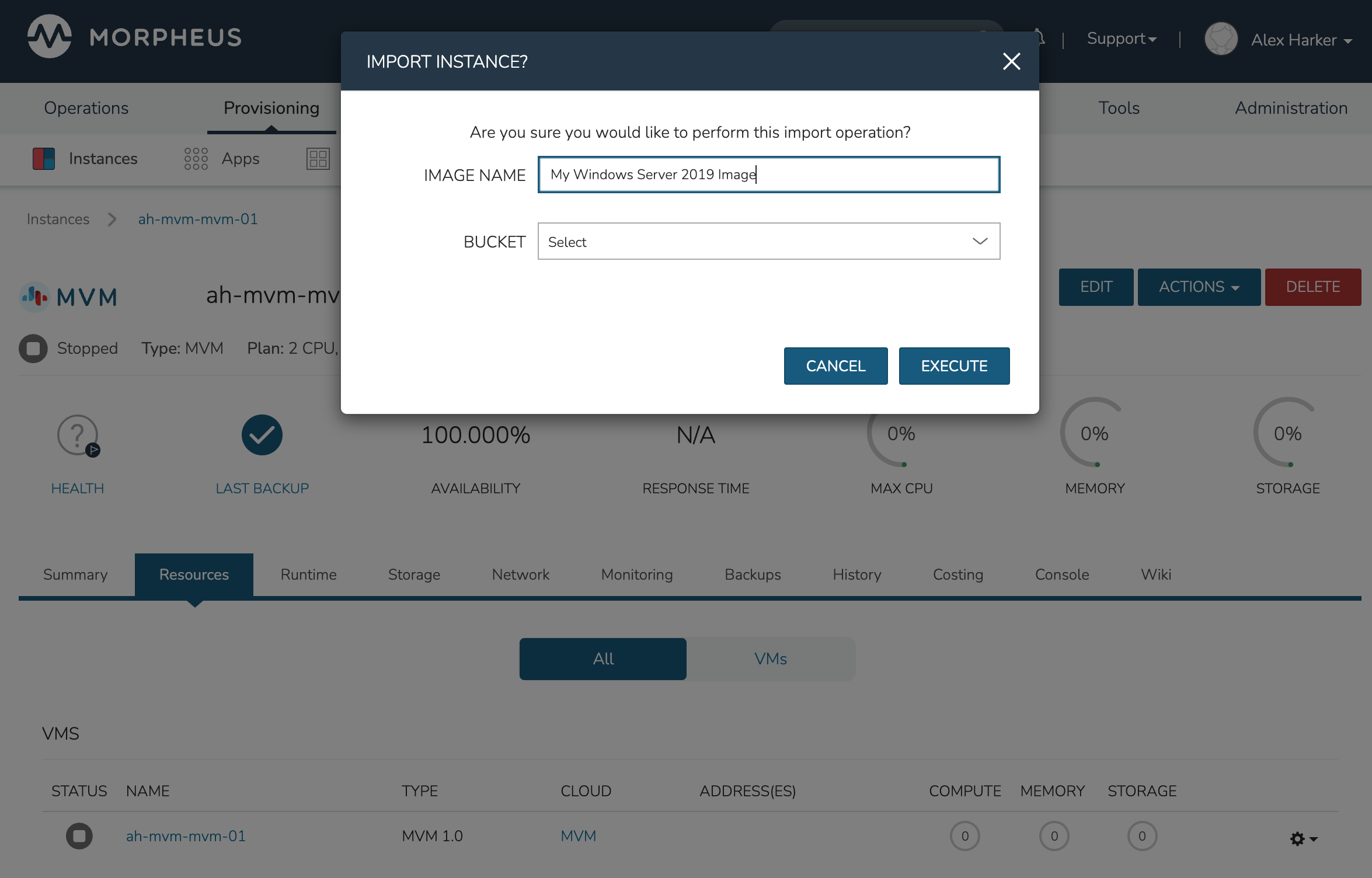
We’re now done configuring Windows and the console window can be closed. We’ll move on to creating a template from the VM we just configured. Begin by opening an SSH session into the HPE Morpheus Enterprise appliance server. Confirm jq is up to date on the appliance box (apt install jq). Then, go ahead and stop the running Windows VM. We can do this from the Instance detail page in HPE Morpheus Enterprise. Click ACTIONS and then “Stop Server.” Still on the Instance detail page, click ACTIONS and then “Import as Image.” This will perform a snapshot and create a new Virtual Image (Library > Virtual Images).
The Virtual Image is not usable until it’s in an active status and the UI indication may display an active status even before it’s fully ready. If it’s “SAVING” or “QUEUED,” it is still being prepared and saved. To determine the current status of the Virtual Image, check with a call to HPE Morpheus Enterprise API like the one below. When the return output lists a status of “Active,” the image is ready to be provisioned from.
curl -k --request GET --url https://xx.xx.xx.xx/api/virtual-images/<id>
--header 'accept: application/json' --header 'authorization: Bearer xxx-xxx-xxx-xxx-xxx' |
jq '.virtualImage.status'
Once saved, additional configurations are needed on the Virtual Image in HPE Morpheus Enterprise. Edit the new Virtual Image and check the following configurations:
MINIMUM MEMORY: Set as appropriate
SYSPREPPED/GENERALIZED IMAGE?: Checked
INSTALL AGENT?: Checked
USERNAME: Remove if present
PASSWORD: Remove if present
VIRTIO DRIVERS LOADED?: Checked
All other checkbox-type configurations not mentioned in the above list should be unchecked. Click SAVE CHANGES.
At this point all image preparation steps are completed. HPE Morpheus Enterprise library items can now be created from this image by adding new Node Types, Layouts, and Instance Types. The complete steps for building a library item go beyond the scope of this particular guide but more detail on that process is available elsewhere in HPE Morpheus Enterprise UI documentation. Once the library items are created, new Instances may be provisioned complete with HPE Morpheus Enterprise Agent installed.
Hardware Passthrough
HPE Morpheus Enterprise includes hardware passthrough and pooling support for VMs provisioned to HVM Clusters. This support extends to GPU, USB and NVME devices. In order to be usable, such devices must be attached to a HVM Host or to multiple HVM Hosts. HPE Morpheus Enterprise includes controls to detach hardware devices from the underlying OS on the hypervisor host and add them to a pool where they are available for consumption by VMs. GPU hardware can be attached to VMs at provision time through custom Service Plans or on an ad-hoc basis by manually attaching hardware to existing VMs. Other supported hardware types must be past through to the VM after provisioning.
Creating Service Plans
When utilizing GPU hardware, it may be most convenient to use a custom Service Plan. This allows administrators to pre-configure the number of discrete hardware cards to attach to the VM at provision time. Once provisioned, the specified number of GPUs will be attached to the VM. For workloads which are provisioned and torn down regularly, this will save additional steps of manually attaching GPUs available from the pool. On teardown, attached devices of all types are released back to the pool. Though in some cases utilizing Service Plans may be most convenient, as you’ll see in the next sections it is not strictly required. It is also possible to manually attach GPUs or other hardware types on any existing VM runnning on HVM Clusters.
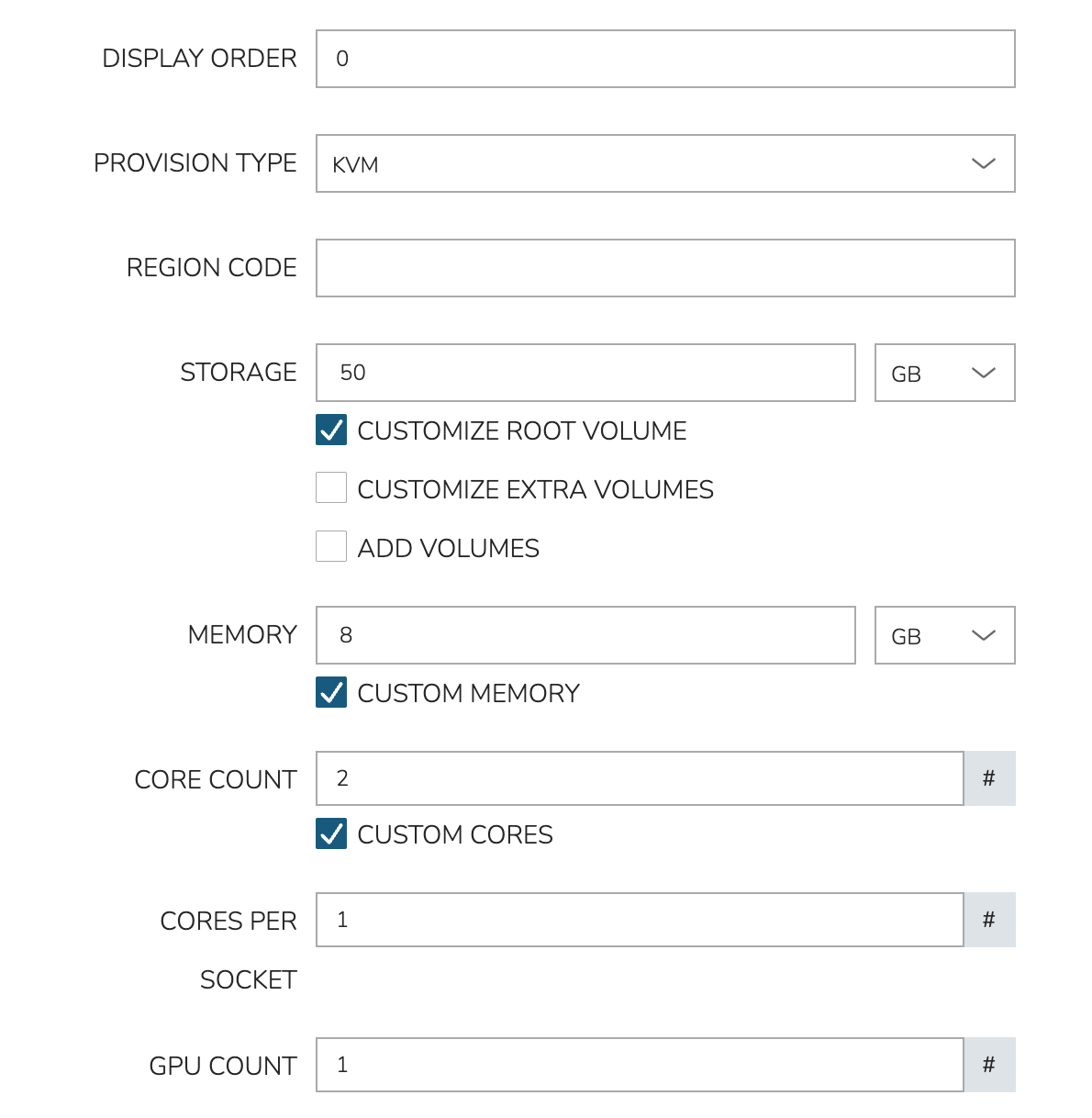
To create a new Service Plan, navigate to Administration > Plans & Pricing. Click + Add and then Service Plan. In the New Service Plan modal, first set the PROVISION TYPE configuration to “KVM.” This will update the available configuration fields and reveal the GPU COUNT configuration. Use this configuration to set the number of GPU hardware cards which should be attached to provisioned VMs using this Service Plan. All other configuration fields for Service Plans go beyond the scope of this guide. Consult Service Plans documentation for additional details specific to Service Plans.
Viewing and Assigning Hardware Devices
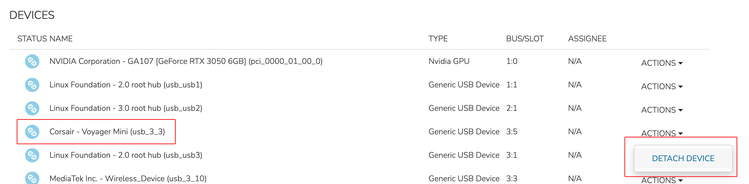
Hardware Devices are surfaced at the Host detail level and the VM (server) detail level through a Devices tab. The Host detail will show all attached hardware devices and their current status: Attached (to the host), detached (from the host), or assigned (to a VM). The VM detail will show only hardware devices currently attached to that VM. To begin consuming hardware devices with HVM Cluster VMs, look again at the list in the Devices tab on the Host detail page. Detach a piece of hardware from the host using the ACTIONS dropdown for that piece of hardware. As shown in the screenshot below, DETACH DEVICE is selected for a USB device.
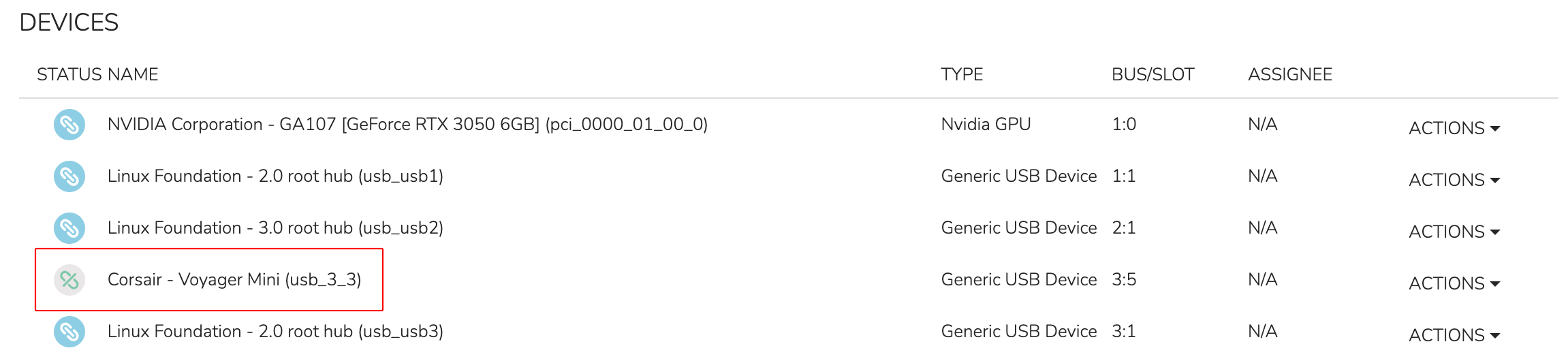
Once detached, the status of the device is changed to “Detached” (see screenshot below) and the device is available for consumption by VMs running on this host.
To assign the hardware to a specific VM, click the ACTIONS dropdown once again for the now-detached hardware. Now, click ASSIGN DEVICE.

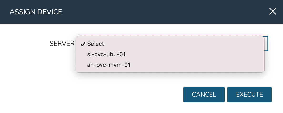
Within the ASSIGN DEVICE modal that will appear, select the server for device assignment and click EXECUTE.
The icon and status for the device in the hardware list has now changed to “Assigned.” If we then open a console session with this VM, we can see the USB device is assigned successfully and is usable by the guest OS.

The same process can be used to detach and assign GPU or NVME devices.
GPU Passthrough Example
In a previous section, a Service Plan was created which consumes a GPU when a VM is provisioned using that Plan. This section shows an example provisioning a workload using that Plan and a GPU-accelerated workload running on the VM. In this example, there is an Nvidia GeForce RTX 3050 connected to one of the HVM Hosts. By passing the GPU hardware through to a provisioned VM, hardware-accelerated AI workloads can be run on the VM.
Begin by navigating to Provisioning > Instances. The list of all currently-managed Instances is here along with high level information (power state, etc). To begin a new Instance, click + ADD. Choose type HVM and click NEXT. On the next pane, choose the Group and Cloud in which your desired HVM Cluster resides, name the Instance, and click NEXT.
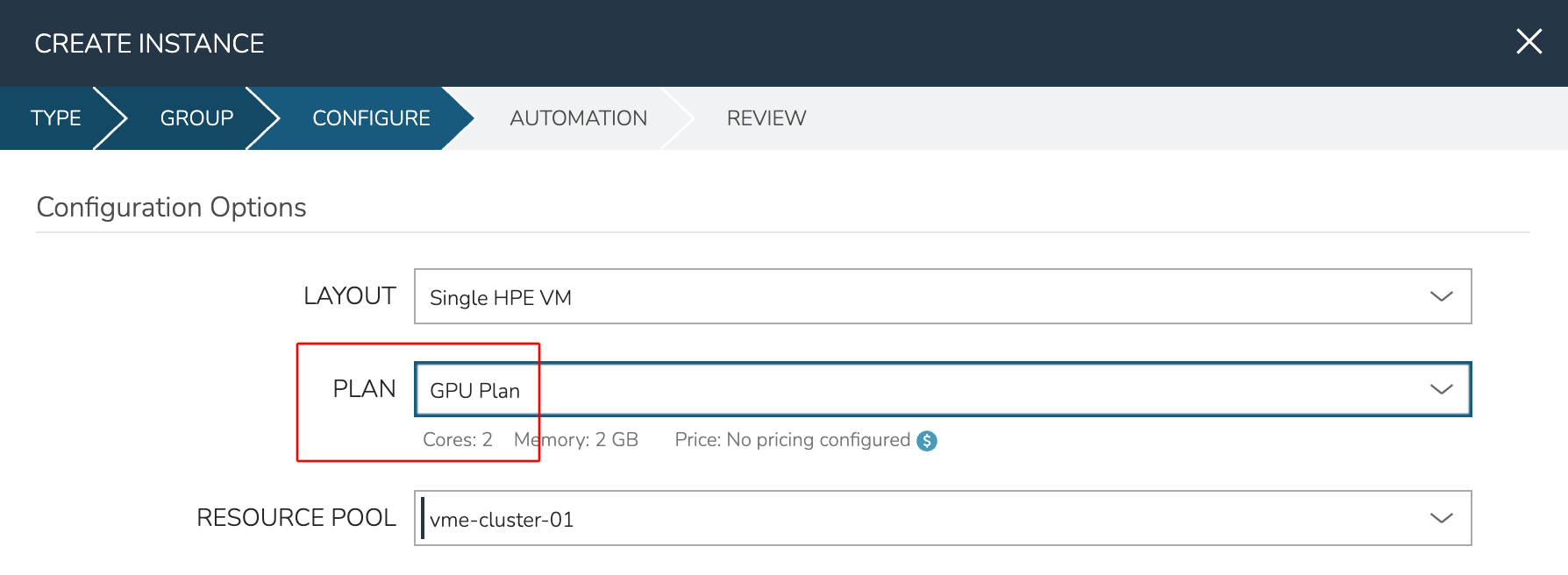
On the CONFIGURE tab, the main thing to note for this example is the PLAN configuration. This dropdown contains some default Plans that are included with HPE Morpheus Enterprise and compatible with the HVM provisioning technology (named “1 CPU, 1GB Memory”, etc). This dropdown also includes user-created Plans, such as those you’ve created to consume GPU hardware. In the screenshot below, you can see the “GPU Plan” was selected.
From here, complete the Instance provisioning wizard selecting any automation or lifecycle configurations and wait for the Instance provisioning to complete.
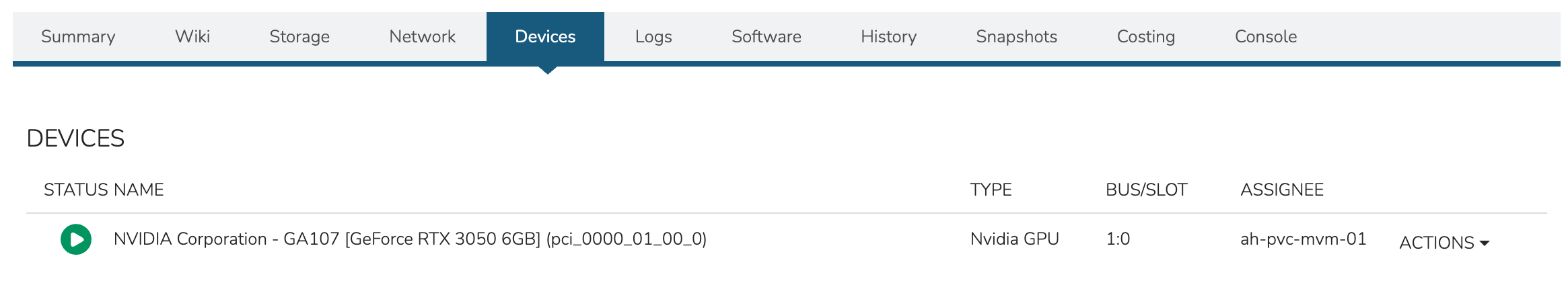
With provisioning complete, check the attached device(s) from the HPE Morpheus Enterprise UI. This is done from the VM level rather than the Instance level. From the Instance detail page, click on the Resources tab. Click on the name of the desired VM to access the VM detail page. Click on the Devices tab. As in the screenshot below, the attached GPU should be shown.
To go further, open a console session to the new VM either through HPE Morpheus Enterprise UI or by connecting to the VM over SSH from a local terminal session. Use the lspci command to view all devices connected to PCI buses. The attached GPU should be shown here as it is in the UI.
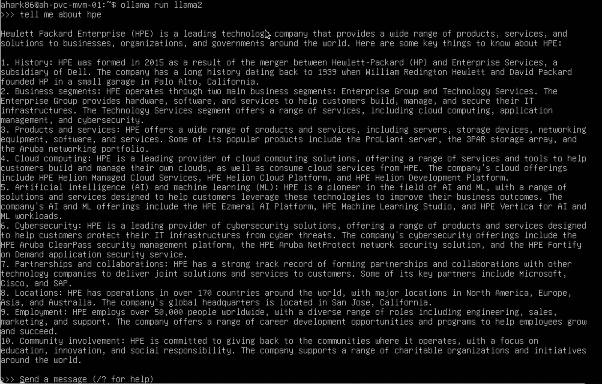
At this point, the VM is ready to run GPU-accelerated workloads normally. To test this, I’ll run Ollama which is an open-source tool designed to make it easy to run large language models (LLMs) locally. In the screenshot below, see the AI chatbot response to an input. This result took only a few seconds thanks to GPU hardware acceleration.
With the request completed, we can run the ollama ps command which confirms the model was running under GPU acceleration.

Kubernetes Clusters
Requirements
Agent installation is required for Master and Worker Nodes. Refer to Morpheus Agent section for additional information.
- Access to Cloud Front, Image copy access and permissions for System and Uploaded Images used in Cluster Layouts
Image(s) used in Cluster Layouts must either exist in destination cloud/resource or be able to be copied to destination by Morpheus, typically applicable for non-public clouds. For the initial provision, Morpheus System Images are streamed from Cloud Front through Morpheus to target destination. Subsequent provisions clone the local Image.
System Kubernetes Layouts require Master and Worker nodes to access to the following over 443 during K8s install and configuration:
Morpheus Role permission
Infrastructure: Clusters > Fullrequired for Viewing, Creating, Editing and Deleting Clusters.Morpheus Role permission
Infrastructure: Clusters > Readrequired for Viewing Cluster list and detail pages.
Creating Kubernetes Clusters
Provisions a new Kubernetes Cluster in selected target Cloud using selected Layout.
Note
When deploying a highly-available Kubernetes cluster, it’s important to note that HPE Morpheus Enterprise does not currently auto-deploy a load balancer. Additionally, when HPE Morpheus Enterprise runs the kubeadm init command in the background during cluster provisioning, it also sets the --control-plane-endpoint flag to the first control plane node. This is a hard-coded behavior. To accomplish a highly-available cluster, users may wish to update the configured control plane endpoint, such as to a DNS name pointing to a load balancer. We are currently investigating updates to the product that would allow the user to specify such a DNS name prior to kicking off cluster provisioning. Additionally, users can circumvent this issue by configuring and deploying their own custom Cluster Layouts.
HPE Morpheus Enterprise maintains a number of default Kubernetes Cluster Layouts which are updated frequently to offer support for current versions. AKS & GKE Kubernetes versions will dynamically update to the providers supported versions. HPE Morpheus Enterprise also supports creation of custom Kubernetes Cluster Layouts, a process which is described in detail in a later section.
To create a new Kubernetes Cluster:
Navigate to
Infrastructure > ClustersSelect + ADD CLUSTER
Select
Kubernetes ClusterSelect a Group for the Cluster
Select NEXT
Populate the following:
- CLOUD
Select target Cloud
- CLUSTER NAME
Name for the Kubernetes Cluster
- RESOURCE NAME
Name for Kubernetes Cluster resources
- DESCRIPTION
Description of the Cluster
- VISIBILITY
- Public
Available to all Tenants
- Private
Available to Master Tenant
- LABELS
Internal label(s)
Select NEXT
Populate the following:
Note
VMware sample fields provided. Actual options depend on Target Cloud
- LAYOUT
Select from available layouts. System provided layouts include Single Master and Cluster Layouts.
- PLAN
Select plan for Kubernetes Master
- VOLUMES
Configure volumes for Kubernetes Master
- NETWORKS
Select the network for Kubernetes Master & Worker VM’s
- CUSTOM CONFIG
Add custom Kubernetes annotations and config hash
- CLUSTER HOSTNAME
Cluster address Hostname (cluster layouts only)
- POD CIDR
POD network range in CIDR format ie 192.168.0.0/24 (cluster layouts only)
- WORKER PLAN
Plan for Worker Nodes (cluster layouts only)
- NUMBER OF WORKERS
Specify the number of workers to provision
- LOAD BALANCER
Select an available Load Balancer (cluster layouts only) }
- User Config
- CREATE YOUR USER
Select to create your user on provisioned hosts (requires Linux user config in HPE Morpheus Enterprise User Profile)
- USER GROUP
Select User group to create users for all User Group members on provisioned hosts (requires Linux user config in HPE Morpheus Enterprise User Profile for all members of User Group)
- Advanced Options
- DOMAIN
Specify Domain override for DNS records
- HOSTNAME
Set hostname override (defaults to Instance name unless an Active Hostname Policy applies)
Select NEXT
Select optional Workflow to execute
Select NEXT
Review and select COMPLETE
The Master Node(s) will provision first.
- Upon successful completion of VM provision, Kubernetes scripts will be executed to install and configure Kubernetes on the Masters.
Note
Access to the sites listed in the Requirements section is required from Master and Worker nodes over 443
After Master or Masters are successfully provisioned and Kubernetes is successfully installed and configured, the Worker Nodes will provision in parallel.
- Provision status can be viewed:
From the Status next to the Cluster in
Infrastructure > ClustersStatus bar with eta and current step available on Cluster detail page, accessible by selecting the Cluster name from
Infrastructure > Clusters
All process status and history is available - From the Cluster detail page History tab, accessible by selecting the Cluster name from
Infrastructure > Clustersand the History tab - From Operations - Activity - History - Individual process output available by clicking i on target process
Once all Master and Worker Nodes are successfully provisioned and Kubernetes is installed and configured, the Cluster status will turn green.
Important
Cluster provisioning requires successful creation of VMs, Agent Installation, and execution of Kubernetes workflows. Consult process output from
``Infrastructure > Clusters - Detailsand morpheus-ui current logs atAdministration - Health - Morpheus Logsfor information on failed Clusters.
Intra-Kubernetes Cluster Port Requirements
The table below includes port requirements for the machines within the cluster (not for the HPE Morpheus Enterprise appliance itself). Check that the following ports are open on Control-plane and Worker nodes:
Protocol |
Direction |
Port Range |
Purpose |
Used By |
|---|---|---|---|---|
TCP |
Inbound |
6443 |
Kubernetes API Server |
All |
TCP |
Inbound |
6783 |
Weaveworks |
|
TCP |
Inbound |
2379-2380 |
etcd server client API |
kube-apiserver, etcd |
TCP |
Inbound |
10250 |
kubelet API |
Self, Control plane |
TCP |
Inbound |
10251 |
kube-scheduler |
Self |
TCP |
Inbound |
10252 |
kube-controller-manager |
Self |
Protocol |
Direction |
Port Range |
Purpose |
Used By |
|---|---|---|---|---|
TCP |
Inbound |
10250 |
kubelet API |
Self, Control plane |
TCP |
Inbound |
30000-32767 |
NodePort Services |
All |
Adding Worker Nodes
Navigate to
Infrastructure - ClustersSelect
v MOREfor the target clusterSelect
ADD (type) Kubernetes Worker- NAME
Name of the Worker Node. Auto=populated with
${cluster.resourceName}-worker-${seq}- DESCRIPTION
Description of the Worker Node, displayed in Worker tab on Cluster Detail pages, and on Worker Host Detail page
- CLOUD
Target Cloud for the Worker Node.
Select NEXT
Populate the following:
Note
VMware sample fields provided. Actual options depend on Target Cloud
- SERVICE PLAN
Service Plan for the new Worker Node
- NETWORK
Configure network options for the Worker node.
- HOST
If Host selection is enabled, optionally specify target host for new Worker node
- FOLDER
- Optionally specify target folder for new Worker node
- Advanced Options
- DOMAIN
Specify Domain override for DNS records
- HOSTNAME
Set hostname override (defaults to Instance name unless an Active Hostname Policy applies)
Select NEXT
Select optional Workflow to execute
Select NEXT
Review and select COMPLETE
Note
Ensure there is a default StorageClass available when using a Morpheus Kubernetes cluster with OpenEBS so that Kubernetes specs or HELM templates that use a default StorageClass for Persistent Volume Claims can be utilised.
Kubernetes Cluster Detail Pages
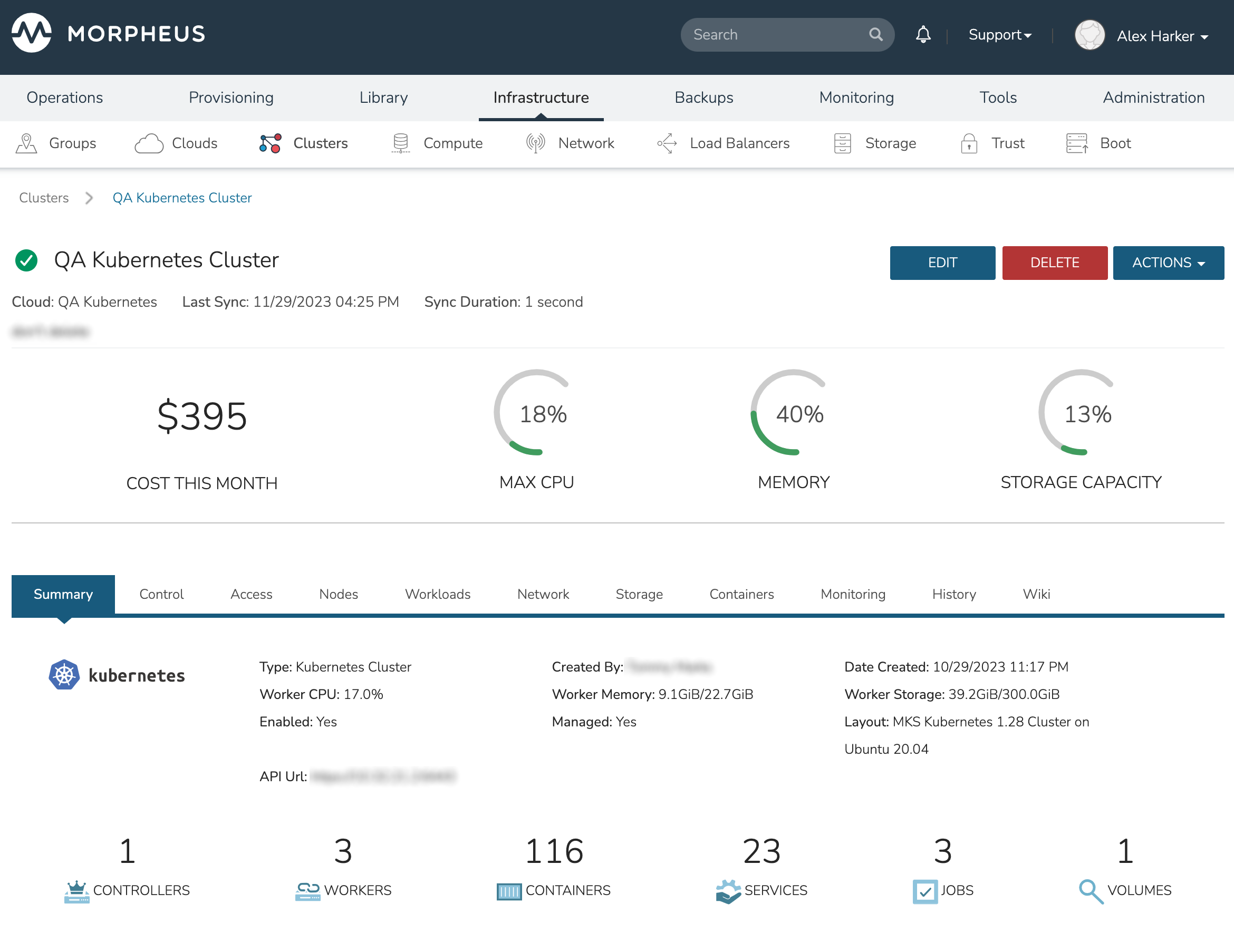
The Kubernetes Cluster Detail page provides a high degree of monitoring and control over Kubernetes Clusters. This includes monitoring of all nodes in the Cluster, kubectl command line, account and role control, workload management, and more. The upper section of the page (which is persistent regardless of the currently-selected tab) provides high level costing and monitoring information, including a current aggregate metric for the CPU, memory and storage use.
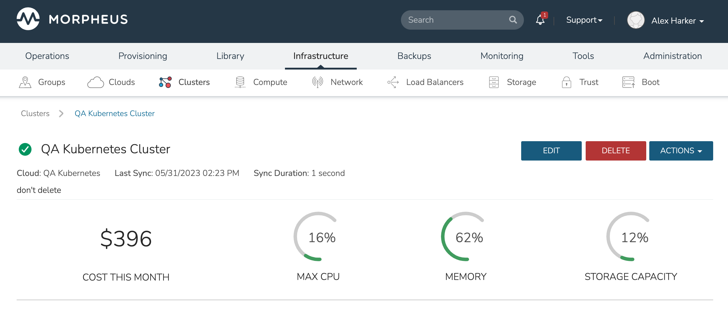
The upper section also includes the ACTIONS menu which includes the following functions:
REFRESH: Forces a routine sync of the cluster status
PERMISSIONS: View and edit the Group, Service Plan, and Tenant access permissions for the cluster
VIEW API TOKEN: Displays the API token for the cluster
VIEW KUBE CONFIG: Displays the cluster configuration
RUN WORKLOAD: Run deployments, stateful sets, daemon sets, or jobs and target them to a specific namespace
UPGRADE CLUSTER: Upgrade the cluster to a higher version of Kubernetes
ADD KUBERNETES WORKER: Launches a wizard which allows users to configure a new worker for the cluster
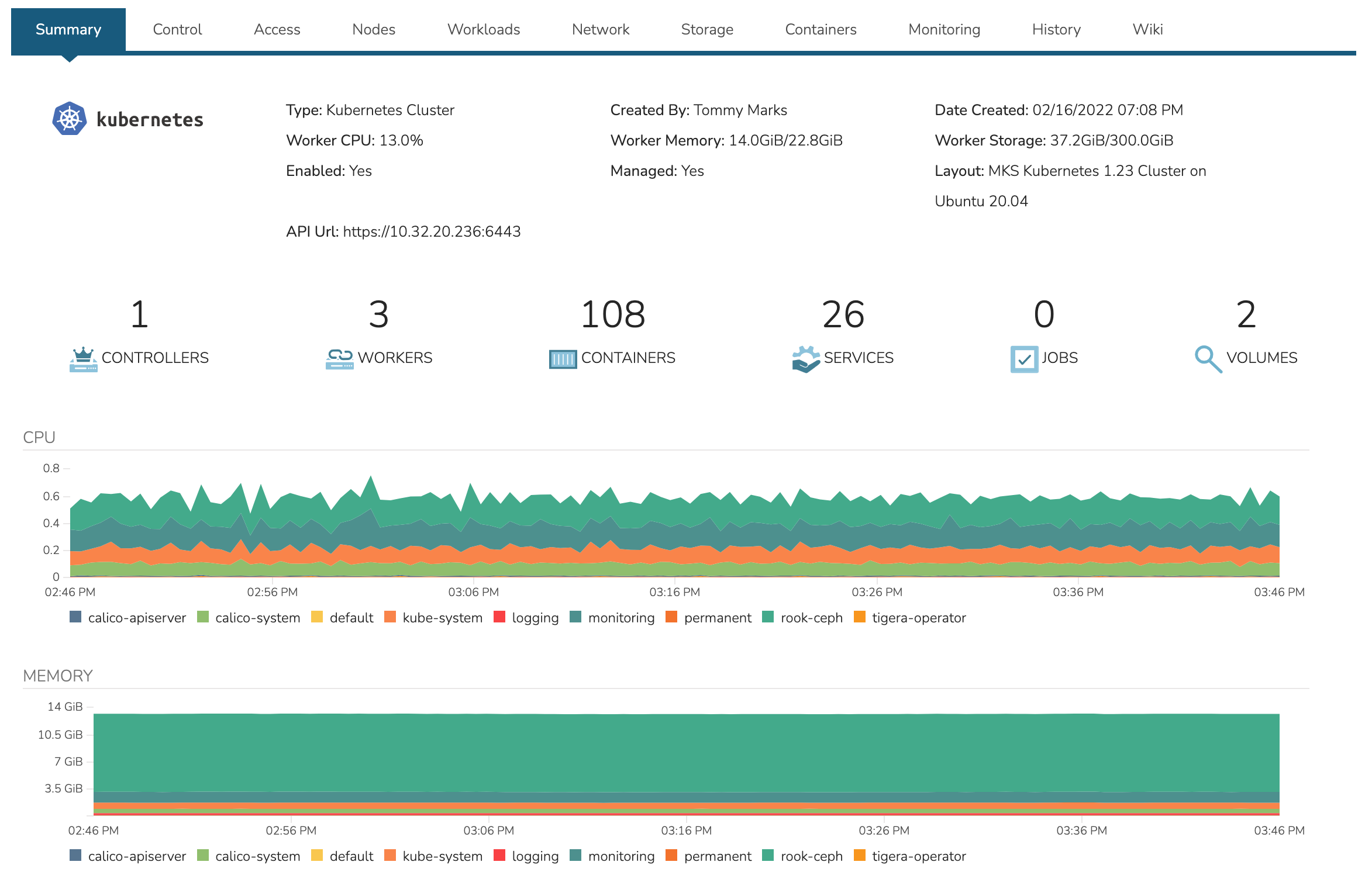
Additional monitoring and control panes are located within tabs, some of which contain subtabs.
The summary tab contains high-level details on health and makeup of the cluster.
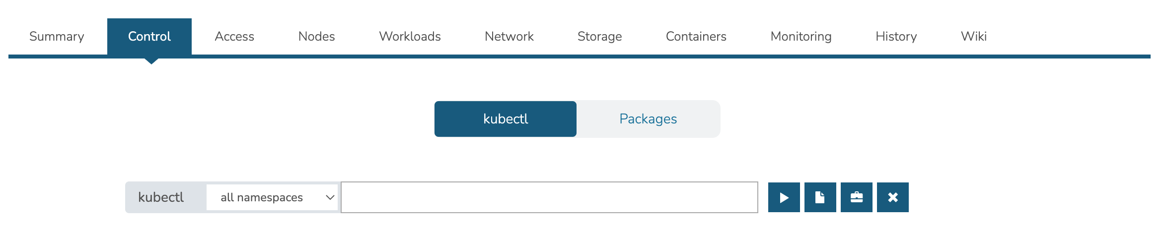
Contains the kubectl command line with ability to target commands to specific namespaces. The Control tab also contains the Packages subtab which displays the list of packages and their versions.
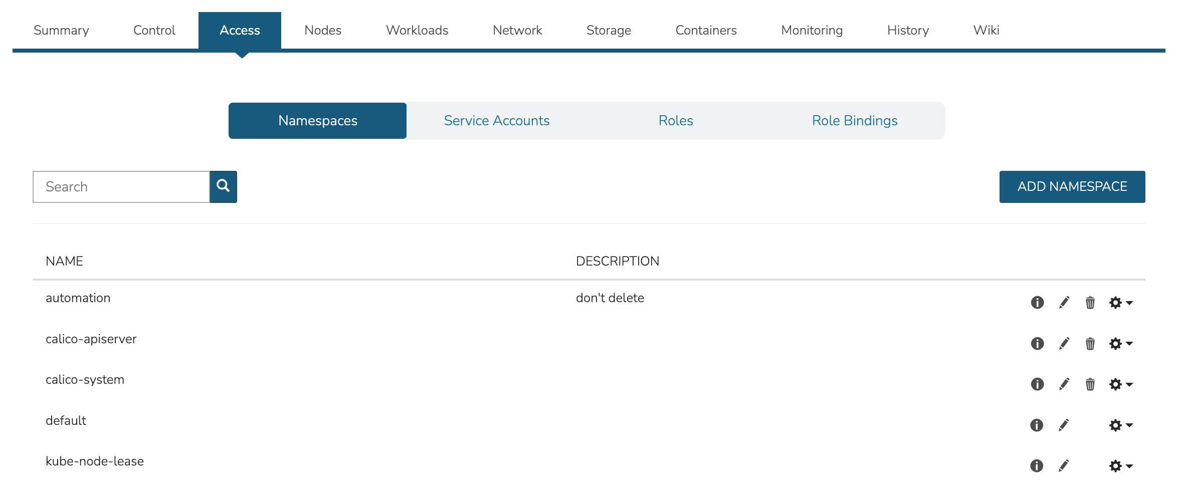
The Access Tab contains view and edit tools for Namespaces, accounts, roles, and role bindings.
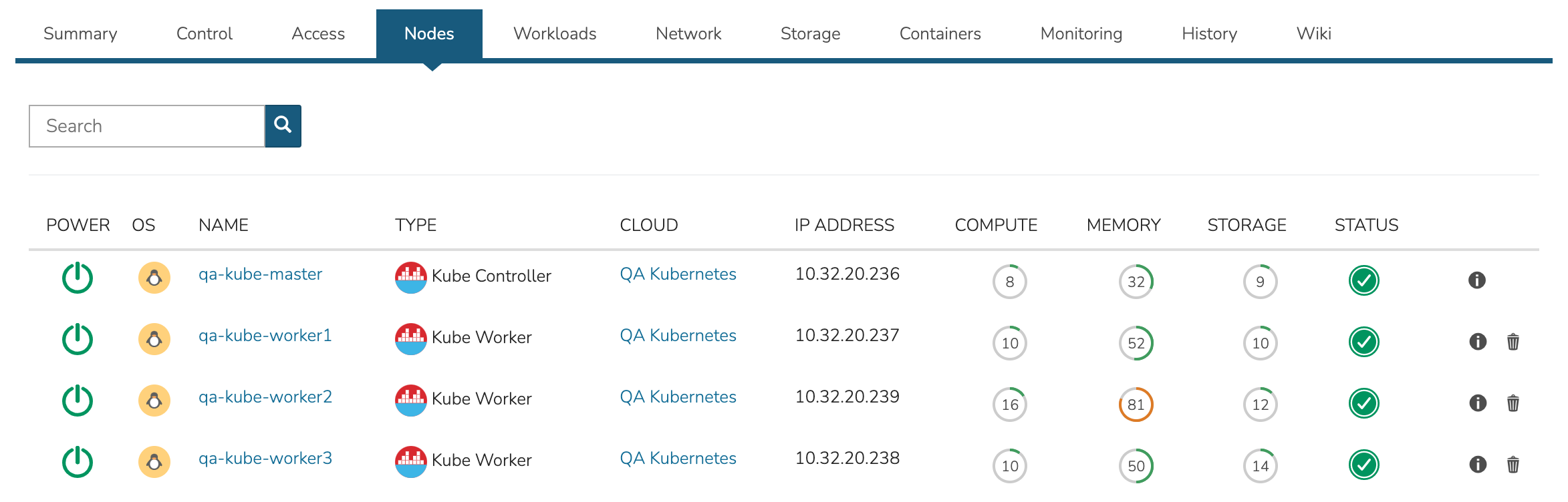
The nodes tab includes a list of master and worker nodes in the cluster, their statuses, and the current compute, memory, and storage pressure on each node.
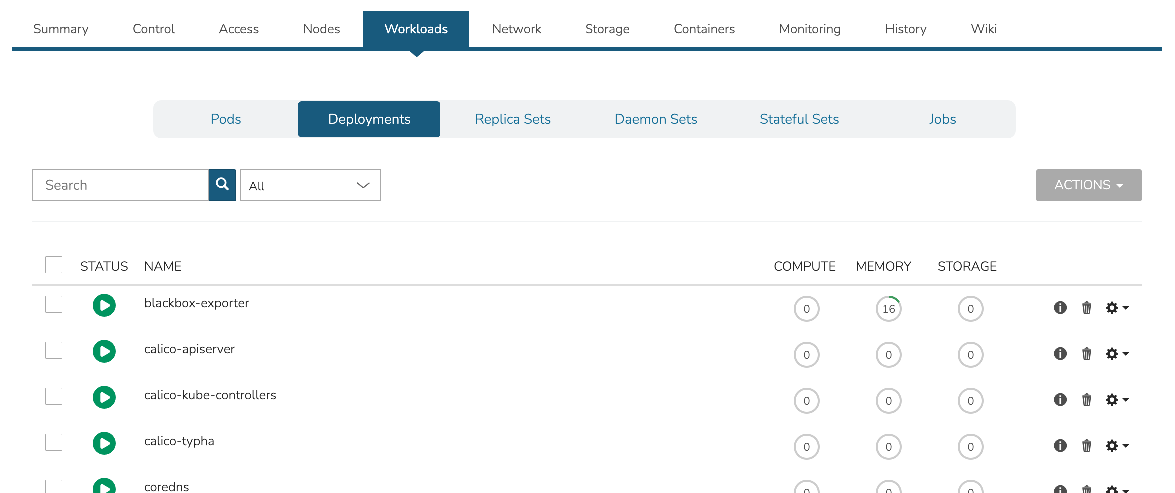
View and edit existing Pods, Deployments, Replica Sets, Daemon Sets, Stateful Sets, and Jobs. Add new Deployments, Stateful Sets, Daemon Sets, and Jobs through the ACTIONS menu near the top of the Cluster Detail Page.
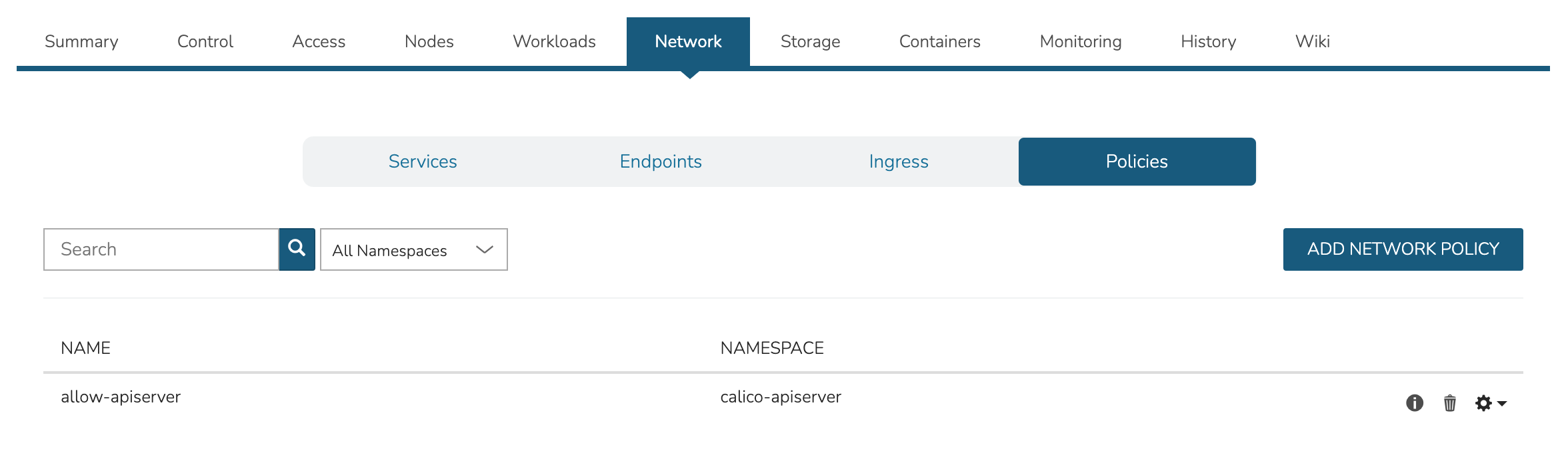
View, add, and edit Services, Endpoints, Ingress and Network Policies
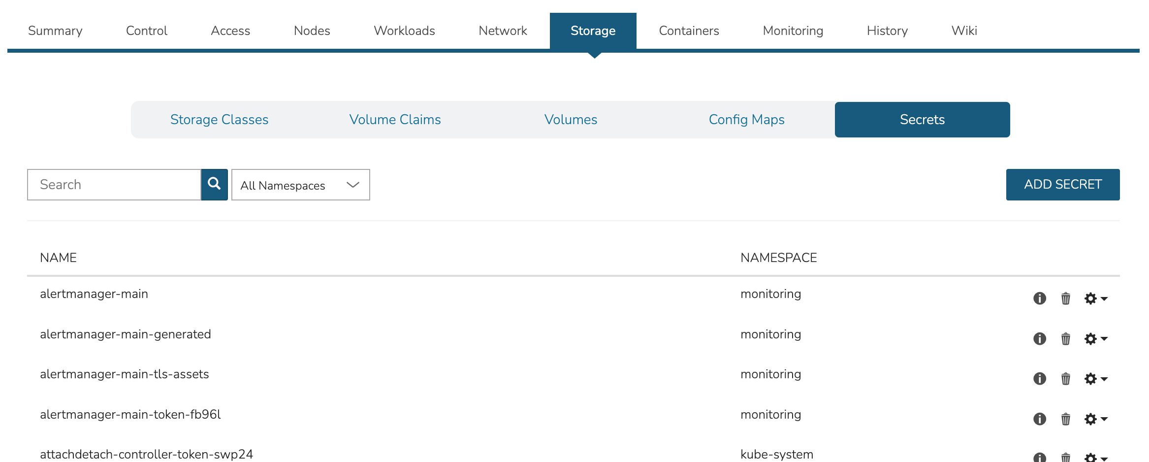
View, add, and edit Storage classes, Volume claims, Volumes, Config maps, and Secrets
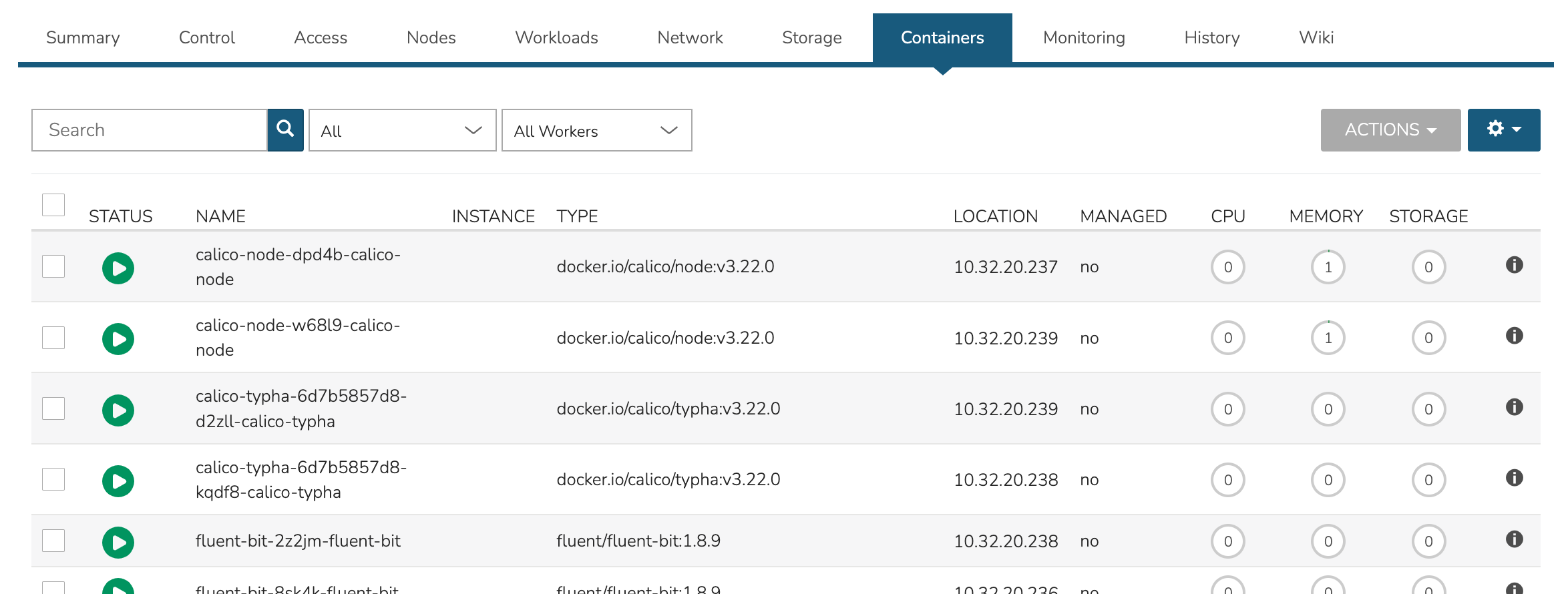
View a list of containers running on the cluster and restart or delete them if needed. This list can be filtered by Namespace or a specific Worker if desired.
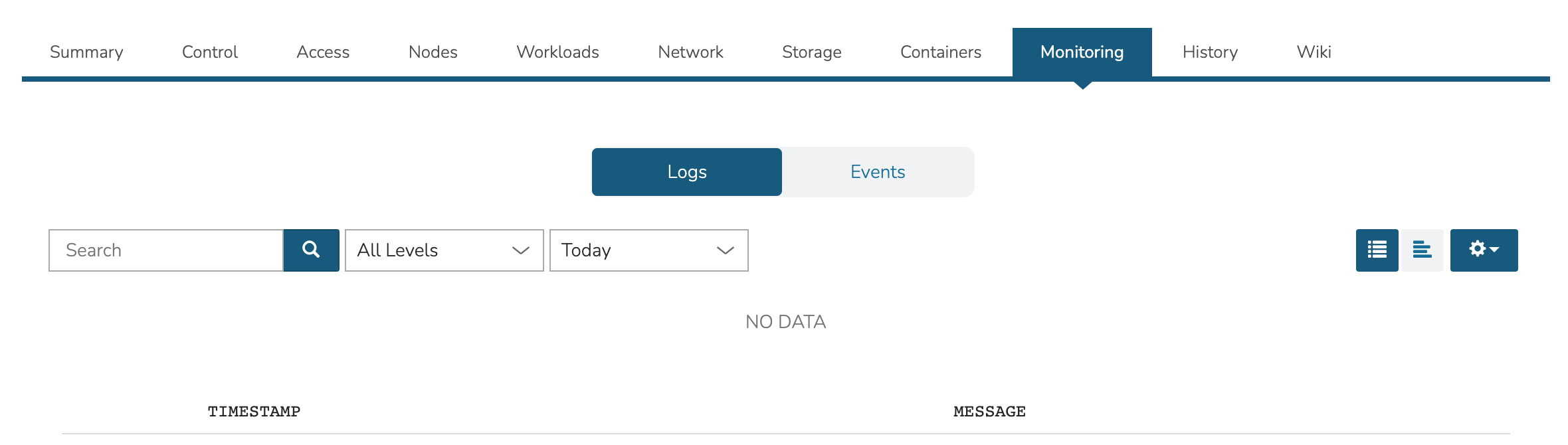
View logs and events with filtering tools and search functionality available.
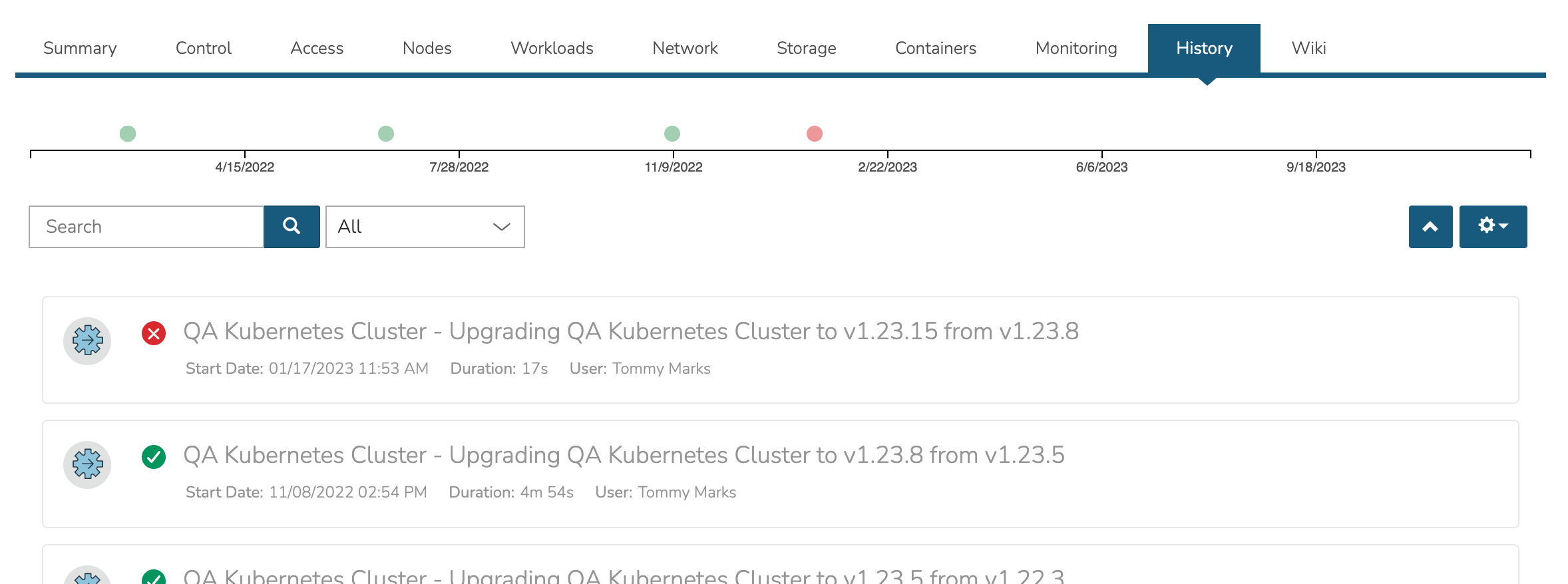
View the Cluster lifecycle history. This includes lists of automation packages (Tasks and Workflows) run against the cluster or its nodes, the success of these scripts and the output.
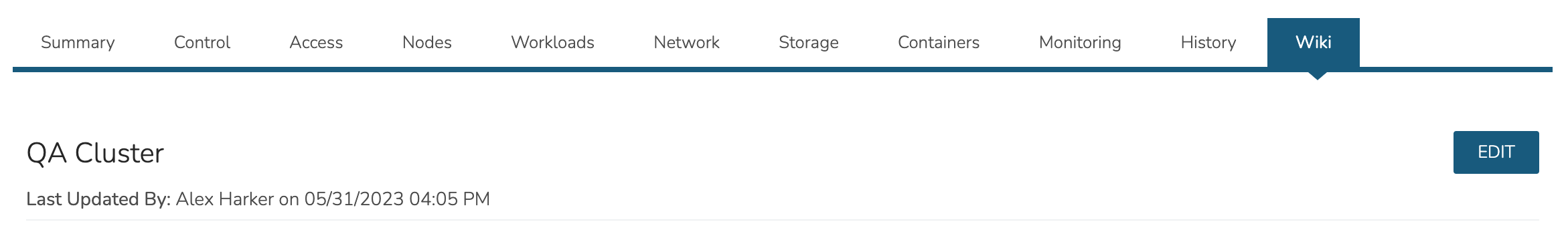
View the HPE Morpheus Enterprise Wiki entry for this Cluster. This Wiki page may also be viewed in the Wiki section (Operations > Wiki). Edit the Wiki as desired, most standard Markdown syntax will be honored allowing the use of headings, links, embedded images, and more.
Adding External Kubernetes Clusters
HPE Morpheus Enterprise supports the management and consumption of Kubernetes clusters provisioned outside of HPE Morpheus Enterprise. These are referred to as External Kubernetes Clusters in HPE Morpheus Enterprise UI. This could be used, for example, to onboard and manage OpenShift clusters. In order to fully integrate the Kubernetes cluster with the HPE Morpheus Enterprise feature set, you may need to create a service account for HPE Morpheus Enterprise. Without first taking that step, some features may not work fully, such as listing all namespaces. The process for creating a service account and integrating the Cluster with HPE Morpheus Enterprise is described here.
First, create the Service Account within the Kubernetes cluster:
kubectl create serviceaccount morpheus
Next, create the Role Binding:
kubectl create clusterrolebinding morpheus-admin \
--clusterrole=cluster-admin --serviceaccount=default:morpheus \
--namespace=default
With those items created, we can gather the API URL and the API token which will be used to add the existing cluster to HPE Morpheus Enterprise in the next step:
kubectl config view --minify | grep server | cut -f 2- -d ":" | tr -d " "
SECRET_NAME=$(kubectl get secrets | grep ^morpheus | cut -f1 -d ' ')
kubectl describe secret $SECRET_NAME | grep -E '^token' | cut -f2 -d':' | tr -d " "
After finishing those steps, we can now create the external cluster in HPE Morpheus Enterprise. Navigate to Infrastructure > Clusters. Click + ADD CLUSTER and then select “External Kubernetes Cluster”. Set the following fields, you will have to advance through the pages of the wizard to see all fields indicated:
GROUP: A previously created HPE Morpheus Enterprise Group
CLOUD: A previously-integrated Cloud
CLUSTER NAME: A friendly name for the onboarded cluster in HPE Morpheus Enterprise UI
RESOURCE NAME: The resource name will be pre-pended to Kubernetes hosts associated with this cluster when shown in HPE Morpheus Enterprise UI
LAYOUT: Set an associated Layout
API URL: Enter the API URL gathered in the previous step
API TOKEN: Enter the API Token gathered in the previous step
KUBE CONFIG: Enter Kubeconfig YAML to authenticate the cluster
The above are the required fields, others may be optionally configured depending on the situation. Complete the wizard and HPE Morpheus Enterprise will begin the process of onboarding the existing cluster into management within HPE Morpheus Enterprise UI. Once things are finalized and statuses are green, the cluster can be monitored and consumed as any other cluster provisioned from HPE Morpheus Enterprise.
Docker Clusters
Provisions a new Docker Cluster managed by Morpheus.
To create a new Docker Cluster:
Navigate to
Infrastructure > ClustersSelect + ADD CLUSTER
Select
Docker ClusterPopulate the following:
- CLOUD
Select target Cloud
- CLUSTER NAME
Name for the Docker Cluster
- RESOURCE NAME
Name for Docker Cluster resources
- DESCRIPTION
Description of the Cluster
- VISIBILITY
- Public
Available to all Tenants
- Private
Available to Master Tenant
- LABELS
Internal label(s)
Select NEXT
Populate the following (options depend on Cloud Selection and will vary):
- LAYOUT
Select from available layouts.
- PLAN
Select plan for Docker Host
- VOLUMES
Configure volumes for Docker Host
- NETWORKS
Select the network for Docker Master & Worker VM’s
- NUMBER OF HOSTS
Specify the number of hosts to be created
- User Config
- CREATE YOUR USER
Select to create your user on provisioned hosts (requires Linux user config in HPE Morpheus Enterprise User Profile)
- USER GROUP
Select User group to create users for all User Group members on provisioned hosts (requires Linux user config in HPE Morpheus Enterprise User Profile for all members of User Group)
- Advanced Options
- DOMAIN
Specify Domain for DNS records
- HOSTNAME
Set hostname (defaults to Instance name)
Select NEXT
Select optional Workflow to execute
Select NEXT
Review and select COMPLETE
EKS Clusters
Provisions a new Elastic Kubernetes Service (EKS) Cluster in target AWS Cloud.
Note
EKS Cluster provisioning is different than creating a Kubernetes Cluster type in AWS EC2, which creates EC2 instances and configures Kubernetes, outside of EKS.
HPE Morpheus Enterprise currently supports EKS in the following regions: us-east-2, us-east-1, us-west-1, us-west-2, af-south-1, ap-east-1, ap-south-1, ap-northeast-3, ap-northeast-2, ap-southeast-1, ap-southeast-2, ap-northeast-1, ca-central-1, eu-central-1, eu-west-1, eu-west-2, eu-south-1, eu-west-3, eu-north-1, me-south-1, sa-east-1, us-gov-east-1, us-gov-west-1
Create an EKS Cluster
Navigate to
Infrastructure - ClustersSelect + ADD CLUSTER
Select
EKS ClusterPopulate the following:
- LAYOUT
Select server layout for EKS Cluster
- PUBLIC IP
- Subnet Default
Use AWS configured Subnet setting for Public IP assignment
- Assigned EIP
Assigned Elastic IP to Controller and Worker Nodes. Requires available EIP’s
- CONTROLLER ROLE
Select Role for EKS Controller from synced role list
- CONTROLLER SUBNET
Select subnet placement for EKS Controller
- CONTROLLER SECURITY GROUP
Select Security Group assignment for EKS Controller
- WORKER SUBNET
Select Subnet placement for Worker Nodes
- WORKER SECURITY GROUP
Select Security Group assignment for Worker Nodes
- WORKER PLAN
Select Service Plan (EC2 Instance Type) for Worker Nodes
- User Config
- CREATE YOUR USER
Select to create your user on provisioned hosts (requires Linux user config in HPE Morpheus Enterprise User Profile)
- USER GROUP
Select User group to create users for all User Group members on provisioned hosts (requires Linux user config in HPE Morpheus Enterprise User Profile for all members of User Group)
- Advanced Options
- DOMAIN
Specify Domain for DNS records
- HOSTNAME
Set hostname (defaults to Instance name)
Select NEXT
Select optional Workflow to execute
Select NEXT
Review and select COMPLETE
GKE Clusters
Provisions a new Google Kubernetes Engine (GKE) Cluster in target Google Cloud.
Note
Ensure proper permissions exist for the Google Clouds service account to create, inventory and manage GKE clusters.
Create an GKE Cluster
Navigate to
Infrastructure - ClustersSelect + ADD CLUSTER
Select
GKE ClusterPopulate the following:
- CLOUD
Select target Cloud
- CLUSTER NAME
Name for the GKE Cluster
- RESOURCE NAME
Name for GKE Cluster resources/hosts
- DESCRIPTION
Description of the Cluster
- VISIBILITY
- Public
Available to all Tenants
- Private
Available to Master Tenant
- LABELS
Internal label(s)
- LAYOUT
Select cluster layout for GKE Cluster
- RESOURCE POOL
Specify an available Resource Pool from the selected Cloud
- GOOGLE ZONE
Specify Region for the cluster
- VOLUMES
Cluster hosts volume size and type
- NETWORKS
Select GCP subnet(s) and config
- WORKER PLAN
Service Plan for GKE worker nodes
- RELEASE CHANNEL
Regular, Rapid, Stable or Static
- CONTROL PLANE VERSION
Select from available synced GKE k8’s versions
- NUMBER OF WORKERS
Number of worker nodes to be provisioned
Select NEXT
Select optional Workflow to execute
Select NEXT
Review and select COMPLETE